


Operation
12 311052E
Operation
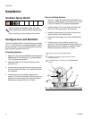
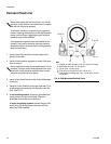
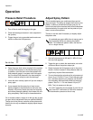
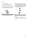
Pressure Relief Procedure
1. Turn off the air and fluid supply to the gun.
2. Close the bleed-type master air valve (required in
the system).
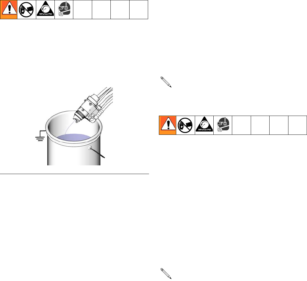
3. Trigger the gun into a grounded metal waste con-
tainer to relieve the fluid pressure.
4. Open the pump drain valve (required in the system)
to relieve fluid pressure in the displacement pump.
In addition, open the drain valve connected to the
fluid pressure gauge (in a system with fluid regula-
tion) to relieve fluid pressure in the hose and gun.
Have a container ready to catch the drainage.
5. Leave the drain valve(s) open until you are ready to
spray again.
6. If you suspect that the spray tip or hose is com-
pletely clogged or that pressure has not been fully
relieved, very slowly loosen the hose end coupling
and relieve pressure gradually, then loosen the cou-
pling completely. Clear the tip or hose obstruction.
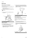
Adjust Spray Pattern
The air-assisted spray gun combines airless and air
spray concepts. The spray tip shapes the fluid into a fan
pattern, as does a conventional airless spray tip. Air
from the air cap further atomizes the fluid and completes
the atomization of the paint tails into the pattern to pro-
duce a more uniform pattern.
The fan air can be used if necessary to slightly adjust
the pattern size.
1. Set the fluid pressure at 300 psi (2.1 MPa, 21 bar)
with the fluid regulator.
2. Trigger the gun to check the atomization; do not be
concerned about the pattern shape yet.
3. Slowly Increase the fluid pressure just to the point
where a further increase in fluid pressure does not
significantly improve fluid atomization.
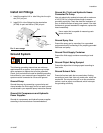
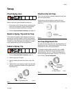
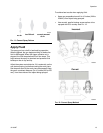
4. Turn on the atomizing air and set the air pressure at
about 10 psi (70 kPa, 0.7 bar). Check the spray pat-
tern, and then adjust the air pressure until the tails
are completely atomized and pulled into the spray
pattern. See F
IG. 11. Do not exceed 100 psi (0.7
MPa, 7 bar) air pressure to the gun.
For a narrower pattern, supply air to the gun fan air inlet
(or open the fan adjustment valve on manifold 288223).
The tip size is the primary controller of the pattern size.
Use the fan air only as needed to slightly adjust the pat-
tern size.
FIG. 10: Pressure Relief
TI8174a
Air-assisted spray guns differ from air spray guns in
that increasing the fan air reduces the pattern
width. To increase the pattern width, use less fan
air or a larger size tip.
For HVLP operation do not exceed 10 psi at the air
cap. Use HVLP verification kit 249140 to measure
the atomization pressure at the air cap.