


Installation
311052E 9
Connect Air Line
1. Install an air/water separator and an air line filter to
ensure a clean, dry air supply to the gun. Dirt and
moisture in the line can ruin the appearance of your
finished piece.
2. Install an air pressure regulator on each gun air sup-
ply line.
3. For manifolds with separate fan and atomization
ports, the gun cylinder, fan, and atomization air must
be supplied and regulated separately. For manual
valve manifolds, only one supply line is required for
both atomization and fan air.
4. Install a bleed-type master air shutoff valve on the
main air line. Install an additional bleed-type valve
on each pump air supply line, downstream of the
pump air regulator, to relieve air trapped between
this valve and the pump after the air regulator is shut
off.
5. Install a bleed-type air shutoff valve on each gun air
supply line, downstream of the gun air regulator, to
shut off air to the gun.
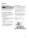
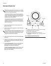
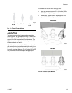
6. For manifolds with separate fan and atomization
ports, connect a separate air supply line to the gun
atomizing air inlet (D) and cylinder air inlet (C). Con-
nect an air supply line to the fan air inlet (E) if
desired. See F
IG. 6. For manifolds with a manual fan
valve, only one supply line is required for both atom-
ization and fan air.
A minimum of 50 psi (0.34 MPa, 3.4 bar) air pres-
sure must be supplied to the cylinder for proper
operation. Set the atomization air as needed for
complete atomization of the entire pattern. The tip
size is the primary controller of the pattern size.
Use the fan air only as needed to slightly adjust the
pattern size.
The bleed-type air shutoff valve is required in your sys-
tem to relieve air trapped between this valve and the
pump after the air regulator is closed. Trapped air can
cause the pump to cycle unexpectedly, which could
result in serious injury.
The gun atomizing and fan air inlets are 3/8 in. (9.5
mm) O.D. tubing compatible. The cylinder air inlet
accepts 1/4 in. (6.3 mm) O.D. tubing.