


-32-
G0456 Variable Speed Wood Lathe
A misaligned headstock will not give you accurate
results and may be dangerous. This procedure
takes approximately 30 minutes to complete and
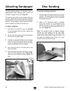
requires you to remove and discard the sandpa
-
per disc if it is installed. If you need help locat
-
ing any parts of the machine, refer to the parts
breakdown.
Tools Needed Qty
Socket or Wrench 12mm ................................... 1
Socket or Wrench
1
⁄2" ........................................ 1
Hex Wrench 6mm ..............................................
1
Hex Wrench 5mm ..............................................
1
Hex Wrench 4mm ..............................................
1
Phillips Screwdriver ...........................................
1
To check headstock/tailstock alignment:
1. DISCONNECT LATHE FROM POWER!
2. Remove the tool rest from the lathe bed.
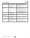
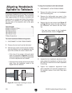
3. With the spur center and live center installed,
slide the tailstock up to the headstock so the
tips of the centers are close to each other.
—If the tips of the centers will touch each
other, as illustrated in Figure 45, the head-
stock and tailstock are already aligned and
no further adjustments are needed.
—If the tips of the centers will not touch each
other, then the headstock needs to be
aligned with the tailstock.
Aligning Headstock
Spindle to Tailstock
Figure 45. Center tips touching to ensure
alignment.
To align the headstock with the tailstock
:
1. DISCONNECT LATHE FROM POWER!
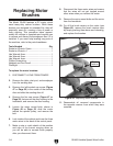
2. Remove the table, dust port, and sandpaper
from the sanding disc.
3. Remove the left-handed cap screw in the
center of the sanding disc and slide the sand
-
ing disc off.
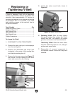
4. Remove the five cap screws (see Figure 47
on Page 33) that secure the disc housing to
the headstock, and remove the disc hous
-
ing.
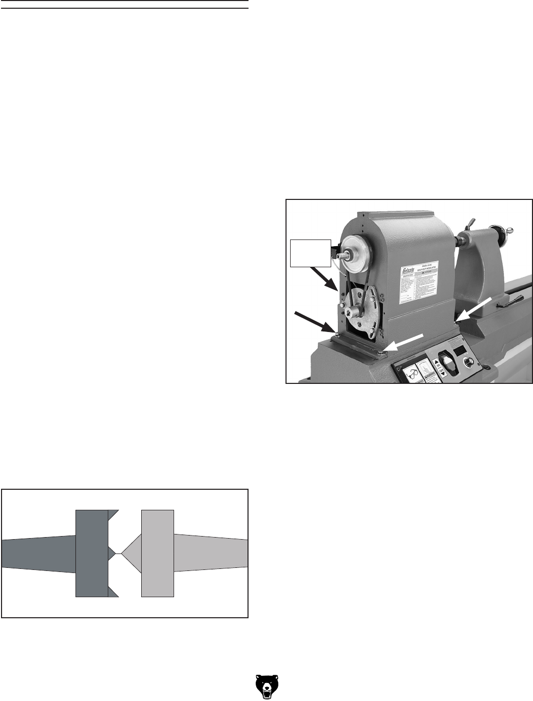
—You now have access to the headstock
adjustment bolts, shown in
Figure 46.
5. Loosen the four headstock adjustment bolts,
and position the headstock so the tips of the
spur and live centers are as close as possible
to touching.
6. Tighten the headstock adjustment bolts
and reassemble all removed components in
the opposite manner from which they were
removed.
Figure 46. Headstock adjustment bolts.
Not
Shown