


Model G0563/G0564 (Mfd. Since 10/11)
-25-
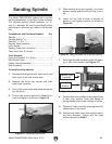
Sanding Spindle
The Model G0563/G0564 comes with a spindle
sanding attachment for sanding curved surfaces.
The included sanding drums measure 1
1
/2", 2",
and 3" in diameter. Be sure to periodically adjust
table height to minimize spot wear on the spindle/
belt.
Components and Hardware Needed: Qty
Spindle .............................................................. 1
Spindle Washer
5
/16" .......................................... 1
Hex Bolt
5
⁄16"-18 x
1
⁄2" ......................................... 1
Spindle Table Assembly .................................... 1
Lock Handle ...................................................... 1
Sanding Drum (dia. of choice) ........................... 1
Table Insert (dia. of choice) ............................... 1
Tools Needed:
Open-End Wrench 10 x 12mm .......................... 1
Hex Wrench 5mm .............................................. 1
Phillips Head Screwdriver .................................. 1
Rod (included) ................................................... 1
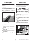
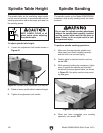
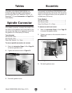
To install sanding spindle:
1. Release the belt guard latch, open cover, and
latch cover to the belt access door.
2. Remove the three cap screws and false
cover from the drum.
3. Line up the screw holes and place the spindle
into the drum.
4. Thread cap screws removed in Step 2 into
drum and tighten, as shown in Figure 19.
Figure 19. Tightening cap screws.
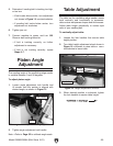
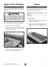
5. Slide sanding drum onto spindle, and insert
spindle washer and hex bolt into top of spin-
dle.
6. Insert rod into hole in base of spindle to
anchor it, and tighten hex bolt, as shown in
Figure 20.
Figure 20. Using included rod to anchor spindle.
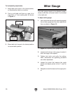
7. Insert spindle table assembly shaft into open-
ing in idler roller bracket (see Figure 21).
8. Thread table lock handle into pre-tapped hole
in idler roller bracket. Note—the handle is
spring loaded and can be used as a ratchet.
9. Remove 4" table insert by removing three flat
head screws in the insert.
10. Replace with table insert that matches sand-
ing drum diameter. Tighten with flat head
screws removed in Step 9.
Figure 21. Spindle table assembly installed.
Spindle Table
Assembly
Idler Roller
Bracket