


-22-
Model G0755 (Mfg. Since 1/13)
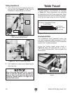
Table Travel
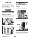
The table travels in two directions, as illustrated
in Figure 19. These movements are controlled
by handwheels and the X-axis power feed. When
using the power feed, travel is limited by the posi-
tion of the limit stops along the front of the table.
X-Axis or Longitudinal Travel
(Left & Right)
Y-Axis or
Cross Travel
(In & Out)
Figure 19. The directions of table movement.
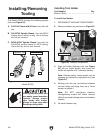
Graduated Dials
The handwheels have graduated scales that
are used to determine table movement in 0.001"
increments. One full revolution of the handwheel
equals 0.100" of table movement.
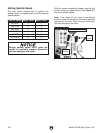
Loosen the locking thumb screw shown in
Figure 20, adjust the graduated dial to “zero” it
for a relative starting point, then re-tighten the
thumb screw.
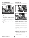
Tilting Headstock
1. Use a 22mm wrench to loosen the three lock-
ing hex nuts (see Figures 17–18), then tilt
headstock to desired angle on tilt scale.
2. Lock headstock in place by re-tightening the
three hex nuts.
When tilting the head back to 90°, you will
need to tram the spindle with the table to
ensure a that it is set perfectly. Refer to the
Tramming Spindle section on Page 38 for
detailed instructions.
Figure 18. Hex nut underneath head.
Hex Nut
Figure 20. Graduated dial and locking thumb
screw.
Thumb Screw
Graduated Dial
Figure 17. Tilt locking hex nut
(one on each side of head).
Hex Nut
Tilt
Scale