


Model G0755 (Mfg. Since 1/13)
-37-
Adjusting Gibs
Gibs are tapered lengths of metal that are sand-
wiched between two moving surfaces. Gibs con-
trol the gap between these surfaces and how they
slide past one another. Correctly adjusting the
gibs is critical to producing good results.
Correctly positioning gibs is a matter of trial and
error and patience. Tight gibs make table move-
ment more accurate but stiff. Loose gibs make
table movement sloppy but easier to do. The goal
of gib adjustment is to remove unnecessary slop-
piness without causing the ways to bind.
Many experienced machinists adjust the gibs just
to the point where they can feel a slight drag in
table movement.
Screws on each end of the gib allow gib adjust-
ment to increase or decrease the friction between
the sliding surfaces.
DISCONNECT MACHINE FROM POWER
BEFORE ADJUSTING THE GIBS!
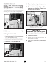
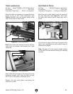
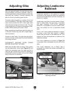
Make sure all table locks are loose. Then, loosen
one gib adjustment screw (see Figure 53) and
tighten the opposing screw the same amount to
move the gib, while at the same time rotating the
handwheel to move the table until you feel a slight
drag in that path of movement.
Figure 53. Location of table gib screws.
Y-Axis Gib Screw
(1 of 2)
X-Axis Gib Screw
(1 of 2)
Adjusting Leadscrew
Backlash
Leadscrew backlash is the amount of freeplay
movement in the leadscrew (when the leadscrew
moves but the table does not) after changing the
direction of rotation.
Leadscrews must have a certain amount of back-
lash to rotate easily, but over time, it increases
with wear. Generally, 0.003"–0.006" leadscrew
backlash is acceptable to ensure smooth move-
ment and reduce the risk of premature thread
wear.
The X- and Y-axis leadscrew backlash is adjust-
ed using a long 4mm hex wrench to tighten/
loosen the cap screw on the leadscrew nut. This
adjusts the force the leadscrew nut exerts on the
leadscrew threads.
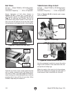
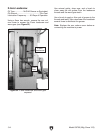
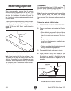
The X-axis leadscrew nut shown in Figure 54
is accessed from underneath the left side of the
table.
The Y-axis leadscrew nut is similar and is
accessed from inside the cabinet underneath the
machine base.
Figure 54. Location of X-axis leadscrew nut for
adjusting backlash.
X-Axis Leadscrew Nut
Cap Screw