


-38-
Model G0755 (Mfg. Since 1/13)
When your operation requires that the spindle
axis be precisely perpendicular to the table, you
must tram the spindle with the table. Simply
adjusting the headstock tilt to the 90° mark on
the tilt scale will not be precise enough for highly
accurate results.
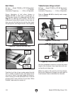
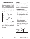
This procedure involves mounting a dial indicator
to the quill or spindle, rotating it around the table,
and adjusting the head position so that the spindle
axis is 90° to the table X-axis, as illustrated in
Figure 55.
Table
Spindle
X-Axis
Z-Axis
90º
Figure 55. Spindle centerline properly trammed
to the table.
Note: Keep in mind that the top surface of your
workpiece will not likely be exactly parallel with the
table top. Depending on your operation, you may
choose to tram the spindle to the top surface of
the workpiece after it is mounted instead of tram-
ming to the table.
Tramming Spindle
Tools Needed Qty
Dial Indicator (with at least 0.0005" resolution) . 1
Indicator Holder (mounted on quill/spindle) ....... 1
Precision Parallel Block (1-2-3 Blocks) .............. 1
Note: A precision-ground plate can be substituted
for the parallel block. The farther the indicator
point can be placed from the spindle axis, the
more accurate the alignment measurements will
be.
To tram the spindle with the table:
1. DISCONNECT MACHINE FROM POWER!
2. Prepare machine by performing the following
tasks:
— Stone table to remove all nicks and burrs,
then clean off all debris. Verify table is
clean by running your hand over the top of
it.
— Position table for the operation you intend
to perform after tramming—preferably cen-
tered with saddle.
— Tighten any table locks that should be tight
during intended milling operation.
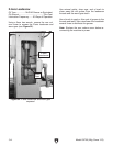
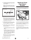
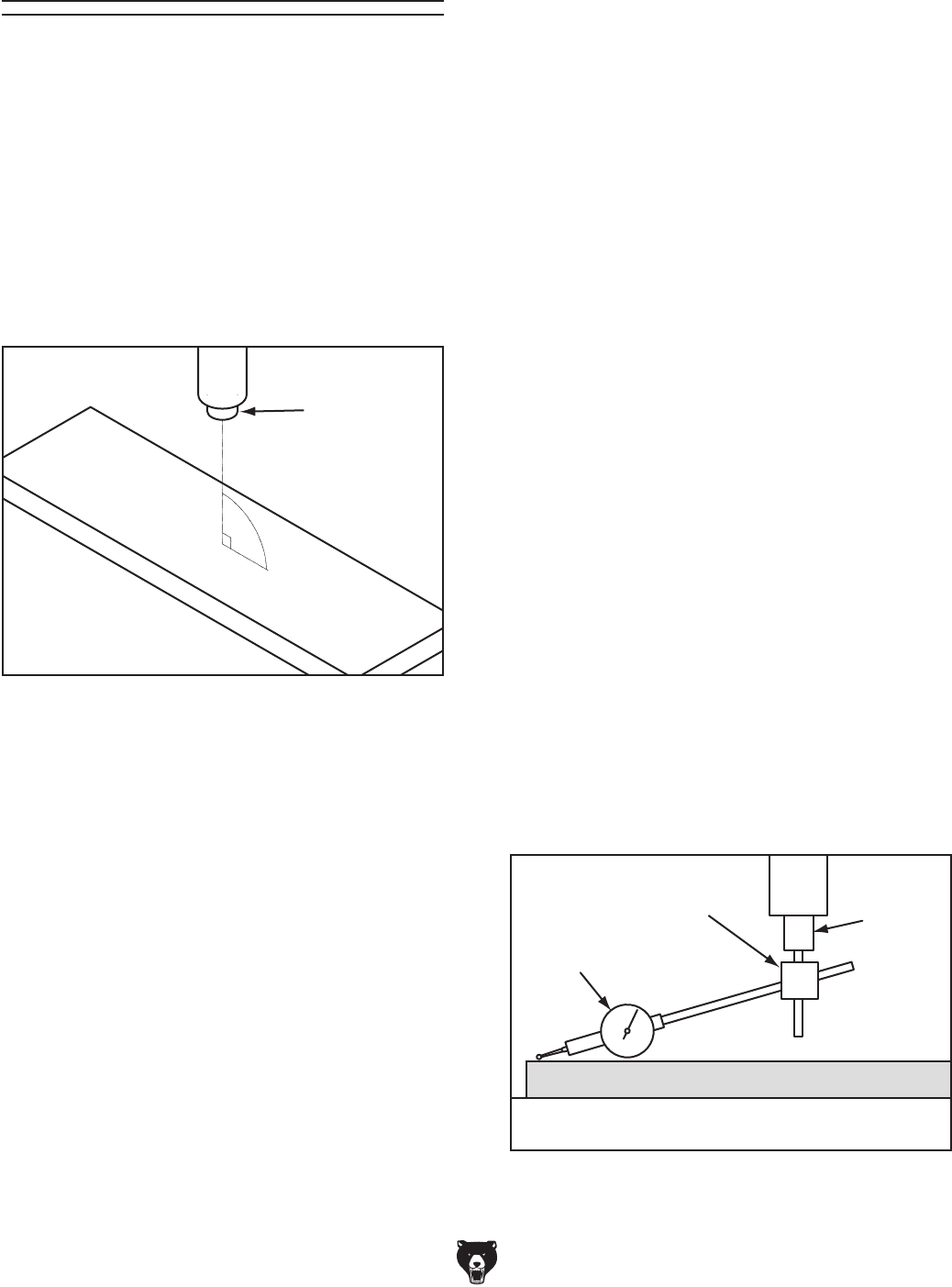
3. Place parallel block underneath spindle.
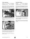
4. Install indicator holder into spindle or onto
quill, then mount indicator onto it so that
the point is as parallel to the block as pos-
sible (see the illustration in Figure 56 for an
example).
Table
Spindle
Dial Indicator
Indicator
Holder
Parallel Block
Figure 56. Dial indicator mounted.