-18-
G1006/7 Heavy Duty Mill/Drill
Power Feed
(G1007 Only)
NOTICE
Use care when aligning the table leadscrew
gears with the gearing on the power feed.
The fit is correct when you can just slightly
wiggle one gear without engaging the other.
If there is too much space between the
gears, teeth can be stripped under heavy
loads. If the teeth mesh too tightly, the sup-
porting bearings in the power feeder will
wear out quickly.
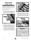
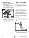
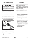
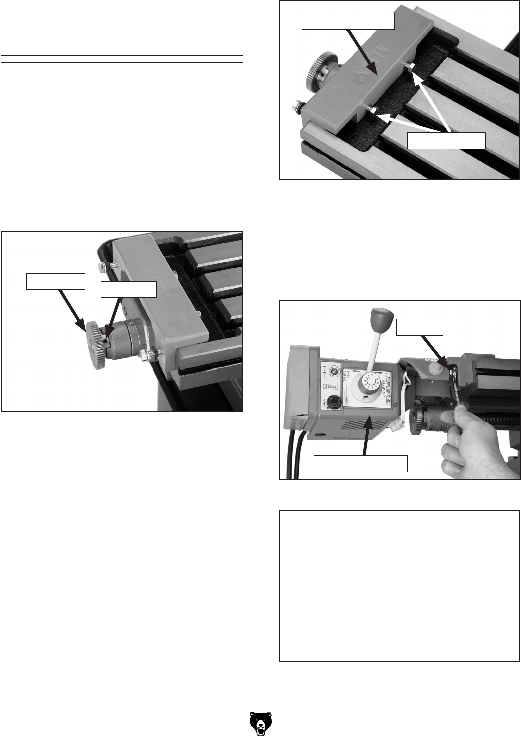
Figure 11. Clamping bracket assembly.
3. Attach the power feed body to the clamping
bracket assembly with the hex bolts. Before
tightening completely, position the power feed
body so the gears mesh perfectly. Tighten the
hex bolts when the gears are in mesh (Figure
12).
Figure 12. Attaching power feed body.
The Model G1007 features a 110V auto-feed
mechanism which allows hands-free, side-to-side
passes while milling. Variable-speed feed control
makes flat surface milling more consistent.
To install the power feed:
1. Attach the 2
1
/4" diameter drive gear to the left
end of the longitudinal table leadscrew. The
gear couplers on the drive gear and table
leadscrew will lock together (Figure 10).
Figure 10. Attaching drive gear.
2. Set the clamping bracket assembly on the left
end of the table. Mark the points on the table
trough where the mounting bolts contact the
table. Remove the clamping bracket assem-
bly and spot drill to give the mounting bolts
a small lip to “bite” without slipping on the
rough cast surface. Set the clamping bracket
assembly back on the end of the table and
tighten down the mounting bolts (Figure 11).
Drive Gear
Set Screw
Clamping Bracket
Mounting Bolts
Power Feed Body
Hex Bolt


