


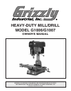
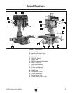

G1006/7 Heavy Duty Mill/Drill
-7-
The information contained herein is deemed accurate as of 8/6/2008 and represents our most recent product specifications.
Due to our ongoing improvement efforts, this information may not accurately describe items previously purchased.
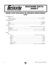
PAGE 2 OF 3Model G1007
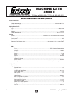
Main Specifications:
Operation Info
Spindle Travel.............................................................................................................................................. 5 in.
Swing................................................................................................................................................... 15-7/8 in.
Longitudinal Table Travel.....................................................................................................................23-1/2 in.
Cross Table Travel.......................................................................................................................................7 in.
Ram Travel.................................................................................................................................................12 in.
Head Travel............................................................................................................................................5-1/4 in.
Head Swivel.......................................................................................................................................... 360 deg.
Max. Dist Spindle To Column.......................................................................................................................8 in.
Max. Dist Spindle To Table........................................................................................................................ 18 in.
Drilling Cap For Cast Iron.......................................................................................................................1-1/4 in.
Drilling Cap For Steel.............................................................................................................................1-1/4 in.
No. Of Vert. Spindle Speeds...........................................................................................................................12
Range Of Vert. Spindle Speeds.........150, 225, 255, 350, 400, 500, 850, 1200, 1500, 1600, 2300, 3000 RPM
No. Of Longitudinal Feeds..................................................................................................................... Variable
Feed Rate....................................................................................................................................... 0 - 140 RPM
Quill Dia.................................................................................................................................................2.950 in.
Table Info
Table Length.............................................................................................................................................. 32 in.
Table Width............................................................................................................................................9-1/2 in.
Table Thickness.....................................................................................................................................1-7/8 in.
No. Of T Slots....................................................................................................................................................4
T Slots Width.........................................................................................................................................0.625 in.
T Slots Height............................................................................................................................................7/8 in.
T Slots Centers.................................................................................................................................... 2-1/16 in.
Stud Size...................................................................................................................................................1/2 in.
Spindle Info
Spindle Taper................................................................................................................................................R-8
End Milling Cap......................................................................................................................................... 3/4 in.
Face Milling Cap...........................................................................................................................................3 in.
Draw Bar Diameter..................................................................................................................................7/16 in.
Draw Bar TPI........................................................................................................................................ 7/16 - 20
Draw Bar Length.................................................................................................................................. 16-1/2 in.
Spindle Bearings......................................................................................................................... Tapered Roller
Lead Screw Info
Lead Screw Diameter............................................................................................................................15/16 in.
Lead Screw TPI...............................................................................................................................................10
Lead Screw Length.................................................................................................................................... 36 in.
Construction
Spindle Housing Const.........................................................................................................................Cast Iron
Table Const............................................................................................................................. Ground Cast Iron
Head Const...........................................................................................................................................Cast Iron
Column Const..........................................................................................................................Ground Cast Iron
Base Const...........................................................................................................................................Cast Iron
Paint..........................................................................................................................................................Epoxy
Other
Collars Calibrated..................................................................................................................................0.001 in.
Column Dia............................................................................................................................................ 4-1/2 in.
Optional Stand..........................................................................................................................................G5944
Mobile Base..............................................................................................................................................G7314