49
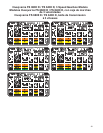
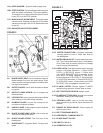
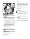
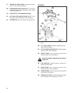
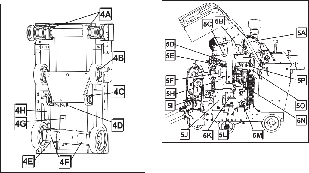
FIGURE 5
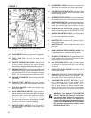
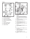
FIGURE 4
4A. BLADESHAFT BEARING SEALS
4B. FRONT WHEEL BEARINGS
4C. FRONT AXLE PIVOT BEARINGS
4D. HYDRAULIC CYLINDER PIVOT PIN
4E. REAR AXLE
4F. HYDRAULIC WHEEL MOTOR
4G. RAISE LOWER CYLINDER
4H. LINEAR ACTUATOR
5A. AIR FILTER ASSEMBLY: Includes
a) Housing
b) Cover
c) Primary Outer Element: Clean or replace when
restriction indicator shows the RED warning.
d) Inner Safety Element: DO NOT CLEAN this lter
element. Replace 1 time per year or if it becomes
damaged.
5B. RADIATOR COOLANT FILL: Fill radiator from this
point. Replace cap if damaged.
5C. ENGINE OIL FILL: One of two ll points.
5D. FUEL HAND PRIMER PUMP: Push to prime fuel
lines to help intial startup or as needed.
5E. FUEL BLEED VALVE: Open to bleed air from
fuel lines.
5F. FUEL FILTER WATER SEPARATOR: See John
Deere engine manual.
5G. – – –
5H. D.C. (direct current) LIFT PUMP: Raises and
lowers the saw.
5I. HYDRAULIC RESERVOIR FILL: Fill and check
hydraulic system uid here.
5J. HYDRAULIC RESERVOIR: 1.5 Quarts
5K. HYDRAULIC FILTER: Filters hydraulic system
uid.


