


52
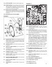
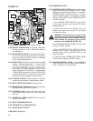
• Turn the Engine Start Switch (1H) to the
“2” (START) position until the engine starts,
then release the switch. It will return to RUN
position. If the engine does not start, repeat
these steps.
• Push the Speed Control Lever (1O)
forward for FORWARD saw movement,
or to the rear for REVERSE saw
movement. The further you push the
lever the faster the speed.
DO NOT OPEN the bypass valve (5M) to
neutral while the saw is parked on a grade
(or hill), The Operator will lose control and
injury or damage could occur.
3 Transport (Blade Removed)
(See Figures 1, 2, and 5)
Turn engine off. Set Speed Control Lever
(1O) to STOP (1BB) position. Remove diamond
blade (2E) before transport.
When moving the saw up and down ramps, with engine
on, use extreme caution.
• To go DOWN a ramp drive the saw FORWARD slowly.
• To go UP a ramp, back the saw in REVERSE slowly.
For steep ramps, always use a winch.
Never stand below the machine.
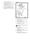
Lifting The Saw. The saw can only be lifted by the factory
installed Lifting Bail (6A).
To Transport By Vehicle:
• Set the Engine Start Switch (1H) in the OFF position.
• Set Speed Control Lever (1O) in the STOP (1BB)
position.
• Push Handle Bars (1B) inward and tighten Knobs (1A).
Block the saw in place or secure it into place
using the factory installed TIE DOWN LUGS
(3H), front and rear to prevent movement
during transport.
4 Check Before Starting
Take into account the working conditions
from health and safety point of view.
• Fuel (Check the engine maintenance manual.) Use
No. 2 Diesel Fuel for normal conditions.
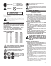
• Check that the engine oil level is correct. Because the
engine often operates at an angle, check the oil level
(with engine horizontal) frequently to ensure that the oil
level never falls below the lower mark on the dipstick.
15W40 CD or CE engine oil is recommended. (6B)
• For start up, refer to the engine manual. See John
Deere Manual OMRG34851
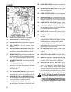
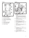
5 Fitting The Blade
(See Figures 1 and 2)
• Set engine Start Switch (1H) to “1” position.
• Raise Machine to a high position using the raise/
lower switch (1P) on the Speed Control Lever (1O)
• Set the Engine Start Switch (1H) to the “0”
(OFF) position.
• Loosen Bolt on Blade Guard Latch (2G).
• Raise Front Half of Blade Guard (2H)
• Loosen Bladeshaft Bolt (2A) Remove Outer
Flange (2B).
• Fit Diamond Blade (2E) to Outer Flange Arbor (2C).
• Install Outer Flange (2B) into the Blade Shaft (2I)
making sure that the Locking Pin (2D) passes through
the Diamond Blade (2E) and into the Inner Flange (2F).
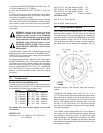
Note the direction of rotation of the blade.
The direction of rotation is shown by an
arrow on both the DIAMOND BLADE (2E) and
the BLADE GUARD (2H). Make sure that the
contact surfaces on the DIAMOND BLADE
(2E), INNER & OUTER FLANGES (2B & 2F)
and BLADE ARBOR (2C) are clean.
• Rotate Outer Flange (2B) and Diamond Blade
(2E) in the opposite direction of blade rotation to
remove backlash.
• Install and tighten Blade Shaft Bolt (2A) using the
Blade Shaft Wrench while rmly holding the Diamond
Blade (2E).
• Lower front half of Blade Guard (2H) and tighten the
Bolt (2G) on the Blade Guard Latch (2G).
The Blade Shaft Bolt (2A) on the Right Hand
side has Left Hand threads. The Blade Shaft
Bolt (2A) on the Left Hand side has Right
Hand threads.
Slip on blade guards are provided with
a safety latch which engages the support
spade and a bolt to retain the rear of
the guard.
Do not operate this saw without the latch
engaged and the bolt installed. Inspect blade
guards and latches frequently. Do not use
if damaged.