


58
15 Accessories
BLADE GUARD CONVERSION KITS:
Use the proper size blade guard for the particular diamond
blade size being operated. The following blade guards
are available for these diamond blade sizes:
Guard Blade Sizes
60” (1500mm) 48” - 60” (1200 - 1500mm)
48” (1200mm) 36” - 48” (1000 - 1200mm)
42” (1000mm) 30” - 42” ( 750 - 1000mm)
36” ( 900mm) 24” - 36” ( 600 - 900mm)
30” ( 750mm) 18” - 30” ( 450 - 750mm)
26” ( 600mm) 14” - 26” ( 350 - 650mm)
18” ( 450mm) 14” - 18” ( 350 - 450mm)
See Blade Size Conversion charts for specific
information.
WEIGHT KITS:
Standard as on: 42” (1000mm), 48” (1200mm) &
60” (1500mm).
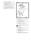
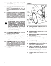
16 Large Diameter Models
The FS8400 can be congured with a 60” (1500mm)
diameter blade capacity. The 60” drive can be ordered
from the factory or can be recongured by ordering the
conversion kit 542 19 96-25. See the Blade Size Conversion
Chart for specics. Depth of cut of 25” can be achieved.
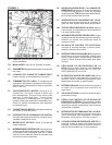
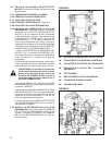
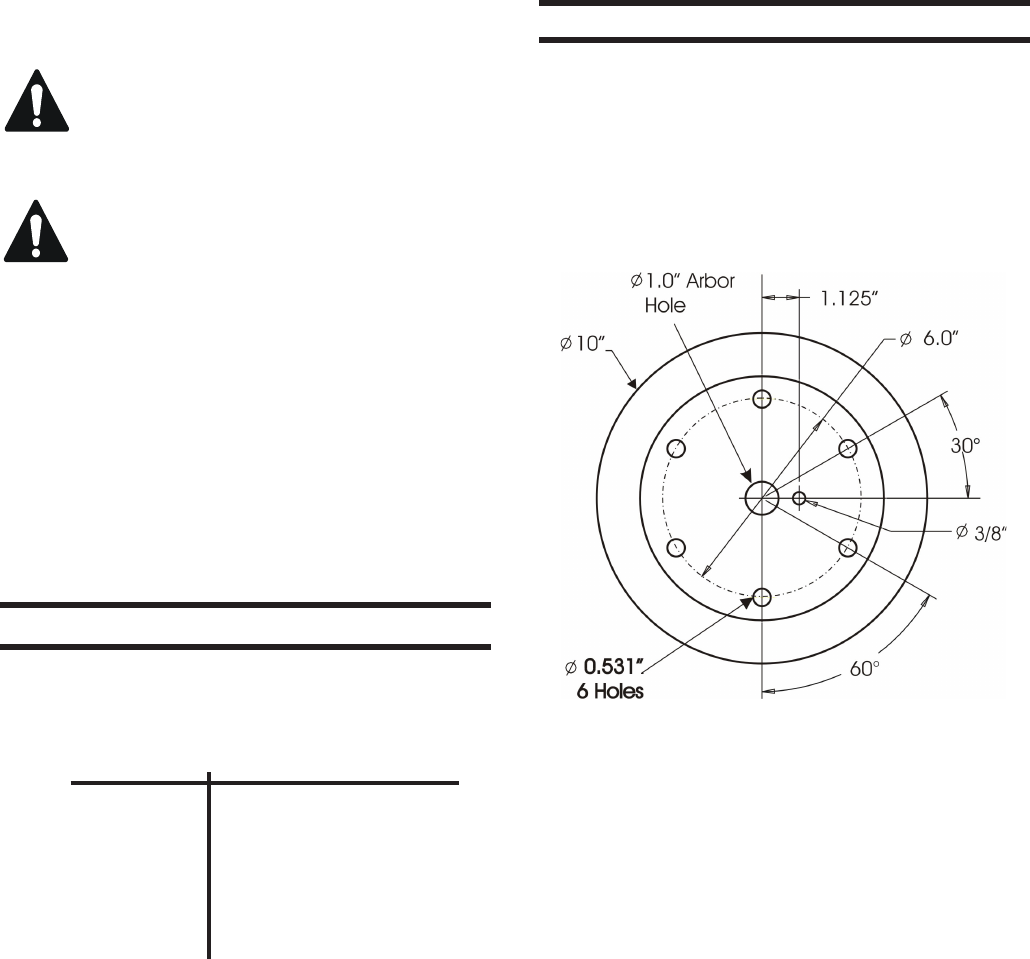
The large diameter model includes a frame extension,
60” blade guard and a blade shaft assembly with 10”
diameter flanges. The Flanges have the following
pattern.
The Blade Hole pattern must match. Six (6), ½-13 x
2.5” long Hex Head Cap Screws pass through the outer
ange through the blade core and thread into the inner
ange supplying the clamping force to hold the blade.
Use ½” lock washers with the clamping bolts. Also use
the 5/8-11 x 4.0” Cap Screw, LH or RH thread through
the center of the ange. Husqvarna will supply blades
with this hole pattern.
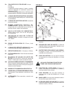
The FS8400, when equipped with a 60” drive system is
very heavy and the machine balance is greatly affected
by installing or removing a blade. To counter the large
balance changes, a weight box is mounted on the left or
right rear of the saws. Weights can be easily removed
and added to quickly adjust the machine balance to meet
the operator’s needs.
542 19 61-72 Kit, Rear weights 2 Bars 42”
542 19 80-22 Kit, Rear weights 3 Bars 48”
542 19 97-57 Kit, Rear weights 6 Bars 60”
(includes: Side weights) 5 Bars w/ handles
OPTIONAL KITS:
542 18 11-17* Dual Light Kit
542 19 96-26 Water Pump Kit
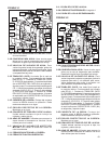
c) Change the ENGINE GEARBOX PULLEY from 4.75”
(121mm) diameter to 4.12” (105mm).
d) Shift the GEARBOX SHIFT LEVER (3-2O) from
2 to 1.
e) Verify that machine drive conguration and blade
shaft speed corresponds with 20-36 drive conguration
information in operation manual.
f) Install the 20-36 drive conguration decals (Decals
504 11 98-09, 542 20 65-49 are required). See the “Decals
and Locations” page of this manual for more information.
See Blade Size Conversion charts for specific
information.
WARNING: Serious injury can occur to the
operator or people in the work area if the
rotational speed (n/min) of the DIAMOND
BLADE (2E) exceeds the maximum speed
(n/min) marked on the DIAMOND BLADE (2E).
WARNING: After Shifting Gearbox, lower
GEARBOX DETENT KNOB (3-2P) or three-
speed ENGINE GEARBOX (3-2A) could
be damaged!
If gearbox seems hard to shift, a slight movement of the
blade shaft may ease movement of GEARBOX SHIFT
LEVER (3-2O) into proper gear. Never shift the Gearbox
(3-2A) with engine running!
Two Neutral positions are available in the Three Speed
ENGINE GEARBOX (3-2A). This gearbox can be shifted
into neutral if the blade rotation needs to be eliminated
while the engine is running. If the machine is equipped
with the optional BLADE CLUTCH (1V), the BLADE
CLUTCH SWITCH (1V) can be moved to the “0” (OFF)
position to eliminate blade rotation while the engine
is running.