


3
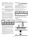
To mount the unit, use the following procedure:
1. Mark the location of the mounting holes.
2. Drill 2-1/4" deep holes using a concrete drill bit sized per the
following table.
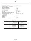
Tank Size Drill Bit
(Gal.) Size
120 1/2"
240 5/8"
NOTE: It may be helpful to use a piece of tape on the
drill bit to mark the proper depth.
3. Drill a hole through the center of each isolation pad.
4. Drive the anchors into the mounting holes with the threaded portion
up.
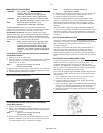
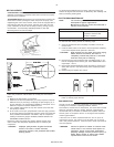
5. Place the isolation pads over the anchors as shown in the
illustration below.
6. Position the compressor over the drilled holes and slowly lower the
unit to the isolation pads.
7. Bolt the compressor to the floor using the 4" long bolts provided.
Torque each bolt in a criss-cross pattern to 10 ft lb.
After the unit has been anchored into position, check the unit for level
by placing a level on the subbase and checking the readings from
side-to-side and from front-to-back. Use metal shims under the "short"
feet if necessary to obtain level.
A = Level concrete floor
B = Foundation bolt / anchor
C = Isolation pad
D = Compressor mounting foot
E = Washer
F = Nut
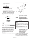
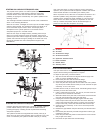
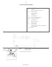
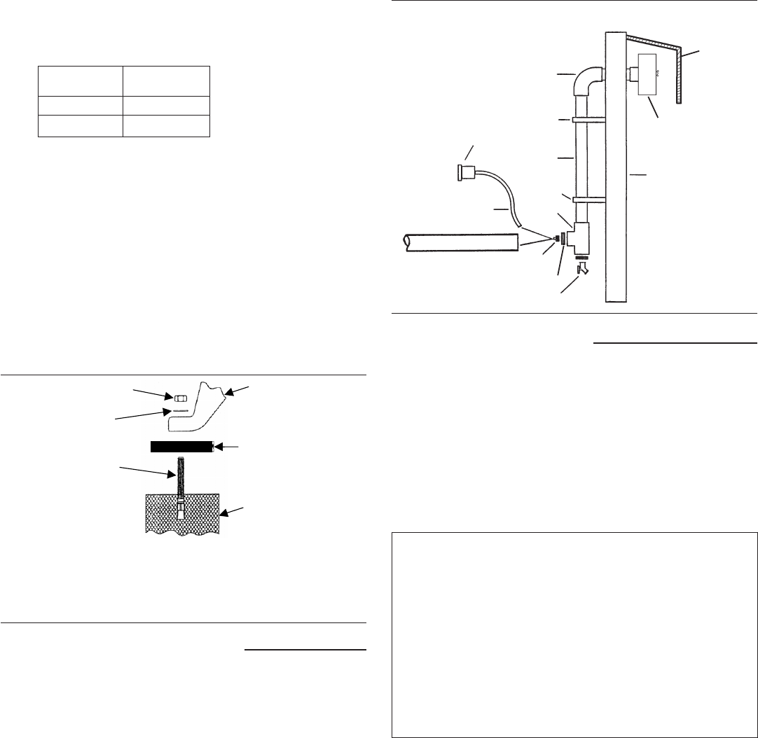
INSTALLING REMOTE AIR INLET PIPING
aCAUTION Do not operate the unit without air inlet
filtration.
If the air around the unit is relatively free of dirt, install the air inlet filter
at the inlet connection at the pump. If the air is dirty, pipe the filter to a
source of clean air. Use PVC plastic tubes for remote inlet piping. Do
not use black pipe or galvanized pipe, as these promote sweating and
rust. Consider installing an in-line type filter for ease of cleaning and
replacement. Make the line as short and direct as possible and as
large, or larger, than the diameter of the inlet connection on the pump.
Do not install piping with a diameter lower than that of the pump intake.
Increase the pipe diameter one size for every 10 feet (3 m) of length
or every 90° bend. Make sure the piping is adequately braced.
If you pipe the filter outdoors, cover it with a hood to prevent the
entrance of rain or snow.
Heavy duty filter elements and filtration equipment are available for fine
airborne dust, such as cement and rock dust.
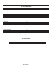
Typical Remote Air Inlet Piping.
INSTALLING DISCHARGE PIPING
aWARNING Do not use plastic pipe, soldered copper
fittings, rubber hose, or lead-tin soldered
joints anywhere in the compressed air
system.
aCAUTION! If you will be using synthetic compressor
lubricant, all downstream piping material and
system components must be compatible. Refer to
the following material compatibility list. If there
are incompatible materials present in your
system, or if there are materials not included in
the list, contact Ingersoll-Rand for
recommendations.
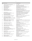
SYNTHETIC COMPRESSOR LUBRICANT
MATERIAL COMPATIBILITY LIST
SUITABLE
Viton®, Teflon®, Epoxy (Glass Filled), Oil Resistant Alkyd, Fluorosilicone,
Fluorocarbon, Polysulfide, 2-Component Urethane, Nylon, Delrin®, Celcon®,
High Nitrile Rubber (Buna N. NBR more than 36% Acrylonitrile), Polyurethane,
Polyethylene, Epichlorohydrin, Polyacrylate, Melamine, Polypropylene, Baked
Phenolics, Epoxy, Modified Alkyds (® indicates trademark of DuPont
Corporation)
NOT RECOMMENDED
Neoprene, Natural Rubber, SBR Rubber, Acrylic Paint, Lacquer, Varnish,
Polystyrene, PVC, ABS, Polycarbonate, Cellulose Acetate, Low Nitrile Rubber
(Buna N. NBR less than 36% Acrylonitrile), EPDM, Ethylene Vinyl Acetate,
Latex, EPR, Acrylics, Phenoxy, Polysulfones, Styrene Acrylonitrile (San), Butyl
NOTE All compressed air systems generate
condensate which accumulates in any drain
point (e.g. tanks, filters, drip legs,
aftercoolers, dryers). This condensate
contains lubricating oil and/or substances
which may be regulated and must be
disposed of in accordance with local, state,
and federal laws and regulations.
GENERAL REQUIREMENTS. The piping, fittings, air receiver tank, etc.
must be certified safe for at least the maximum working pressure of
the unit. Use hard-welded or threaded steel or copper pipes and cast
iron fittings that are certified safe for the unit’s discharge pressure
and temperature. DO NOT USE PVC PLASTIC IN THE COMPRESSED AIR
DISCHARGE LINE. Use pipe thread sealant on all threads, and make up
joints tightly to prevent air leaks.
SUPPORT
SUPPORT
Direct to compressor
air intake (if distance
is less than 6 feet)
OUTSIDE
WALL
DRAIN VALVE
HOOD
ELBOW
BUSHINGS
HOSE
FITTING
TEE
PIPE
INTAKE HOSE
AIR INLET
FILTER
A
B
F
E
C
D
http://air.irco.com