


7
STARTING UNLOADING SYSTEM (MODEL 2000)
The purpose of the system is to relieve cylinder pressure when the
unit stops, permitting it to start against a light load. A light load
increases the life of the driver and belts and also reduces the
possibility of tripping the overload relay. The system operates in the
following manner:
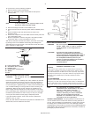
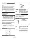
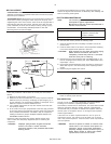
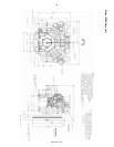
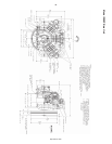
The centrifugal unloader is attached to the end of the crankshaft as
shown in the following illustrations.
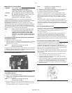
When the unit starts, centrifugal force acts upon the unloader weights
and they swing outward. This permits the plunger and thrust pin to
move inward and the pilot valve to close. The escape path to
atmosphere for the cylinder pressure is now closed and the
compressor pumps air in a normal manner.
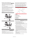
When the unit stops, the weights retract, permitting the thrust pin
spring to move the plunger and thrust pin outward. The thrust pin
opens the pilot valve and the trapped air pressure escapes from the
cylinder and intercooler through a passage in the frame end cover,
through the unloader tube and to atmosphere through the inlet
filter/silencer.
Position of weight and thrust pin when unit is operating.
Position of weight and thrust pin when unit is stopped.
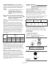
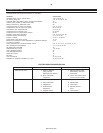
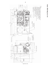
STARTING UNLOADING SYSTEM (2000P)
Pressure lubricated compressors use a hydraulic unloader system to
provide loadless starting. This system has the added feature of
providing emergency unloading should oil pressure be lost during
compressor operation.
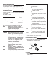
The hydraulic unloader circuit bypasses the auxiliary valve (H) to
direct control air to the head unloaders when oil pressure is lost. This
circuit is controlled by the hydraulic unloader valve (E), a normally
open valve that closes on rising oil pressure. During compressor
operation, the oil pressure holds the hydraulic unloader valve closed.
Head unloader actuation is controlled by the auxiliary valve.
When oil pressure is lost, either due to compressor shutdown or to a
lubrication problem during compressor operation, the hydraulic
unloader opens, actuating the head unloaders (F). This action will
either vent the shut down compressor in preparation for the next
start-up or release compression load to minimize damage if oil
pressure is lost while the compressor is running.
PILOT VALVE ADJUSTMENT
If the pilot valve tube line is excessively hot, it is a good indication that
the pilot valve is leaking and adjustment is required.
To adjust the pilot valve, proceed as follows:
1. Stop the unit and disconnect and tag the electrical supply main
switch to prevent accidental start-up.
2. Remove the pilot valve tube and the tube fittings.
3. Remove the pilot valve body and all existing shims.
4. Screw the pilot valve body back into the frame end cover (without
any shims) until contact with the thrust pin is felt. Advance the pilot
valve body 1/4 to 1/2 turn more.
If contact with the thrust pin cannot be felt, the following steps may be
necessary to locate the contact point:
1. Insert a small instrument (punch, rod, nail, etc.) into the end of the
pilot valve until it contacts the valve stem.
2. While still inserted in the pilot valve, make a mark on the instrument
even with the outside edge of the pilot valve body.
3. Keeping the instrument pressed lightly against the valve stem,
screw the pilot valve body into the frame end cover. When the
mark on the instrument starts moving out away from the edge of
the pilot valve body, contact has been made with the thrust pin.
4. Advance the pilot valve body 1/4 to 1/2 turn more and proceed
with step five.
5. Measure the gap between the pilot valve body and the frame end
cover.
6. Remove the pilot valve body and add enough shims to fill the gap
measured in step five.
7. Screw the pilot valve body back into the frame end cover until the
body is tight on the shims.
8. Reconnect the pilot valve tube and tube fittings.
A = Oil Pump
B = Oil Filter
C = Oil Pressure Gauge
D = Oil Pressure Switch
E = Hydraulic Unloader Valve
F = Head Unloaders
G = Shuttle Valve
H = Auxiliary Valve
http://air.irco.com