


IRN37 - 160K - CC & IRN50 - 200H & IRN75 - 160K - 2S & IRN - 100 - 200H - 2S & IRN 250 - 300H - 2S
http://air.irco.com
21
7.0 INSTALLATION
7.3 ELECTRICAL
CAUTION
This procedure should only be carried out by a qualified electrician, electrical contractor or your local Inger-
soll Rand Distributor or Air Center.
The compressor and drive should be properly grounded
/ earthed in accordance with Local and National Code
requirements.
Installation of this compressor must be in accordance
with recognized electrical codes and any local Health and
Safety Codes.
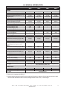
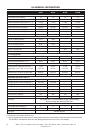
The compressor must have its own isolator situated
adjacent to it. The fuse protecting the circuit and the
compressor must be selected in accordance with local
and national code requirements on the basis of the data
provided in the general information section
Feeder cables should be sized by the customer/electrical
contractor to ensure that the circuit is balanced and not
overloaded by other electrical equipment. The length
of wiring from a suitable electrical feed point is critical
as voltage drops may impair the performance of the
compressor.
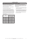
Cable sizes may vary considerably so the mains
terminals will accept up to 50mm2 (1awg) (37/45k
& 50/60H) and up to 90mm2 (3/0awg) (55/75k &
75/100H) cable. The N75K−160K and N100H−200H
machines mains terminals will accept 2 x 120mm2 (4/0
AWG) cables. The N250H−300H−2S machines main
terminals will accept 2 x 400 MCM cables.
Feeder cable connections to incoming terminals
L1−L2−L3 should be tight and clean.
The applied voltage must be compatible with the motor
and compressor data plate ratings.
The control circuit transformer has different voltage
tappings. Ensure that these are set for the specific applied
voltage prior to starting.
A hole is provided for incoming power connection. If it is
necessary to make a hole in the control box in a different
location, care should be taken to not allow metal shavings
to enter the starter and other electrical components
within the box. If another hole is used, the original hole
must be blocked off.
The feeder cable must be suitably glanded into the power
drive module (P.D.M.) electrical box to ensure that dirty air
does not by−pass the filter pads or degrade the cooling
air flow.
On completion of electrical installation, check that blower
motor rotation is correct. N250H−300H utilizes a fan.
This machine is designed for use in heavy industrial
environments, where the electricity supply is separated
from nearby residential and commercial areas. If the
machine is to be used in the light industrial, residential or
commercial environment where the local supply network
is shared, further radio frequency (RF) screening measures
may be required. Consult your local distributor/supplier
for details of the optional RF filter. RF filter supplied as
standard on N250−300H−2S
The compressor has a anti−condensation heater and
thermostat in the electrical box. This circuit can be
connected to an independent electrical supply of either
110V or 230V single phase, dependant on the country
of installation. The supply should be suitable fused
and an independent isolator installed adjacent to the
compressor.
This should be done in accordance with local and national
codes. It is good practice and sometimes mandatory, to
display suitable signs warning that the machine has two
separate electrical supplies which both must be isolated
before any work is attempted.
Alternately it can be supplied from the 110V tapping
of the control transformer and connected as shown on
schematic wiring diagram.