


IRN37 - 160K - CC & IRN50 - 200H & IRN75 - 160K - 2S & IRN - 100 - 200H - 2S & IRN 250 - 300H - 2S
http://air.irco.com
87
10.0 MAINTENANCE
N50/100H N37/75K
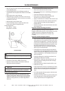
Following are instructions for tilting the cooler away from
the enclosure and cleaning of the cooler.
Remove 6 screws from lower rear fixed panel and
remove panel.
Remove 10 screws from the rear intake panel and
remove panel.
Loosen clamp and disconnect the air inlet hose from
the intake plenum.
Remove intake plenum. Note, plenum is
unsupported, before removing the 8 screws from
the intake plenum, block underside of plenum
prior to removing screws to prevent plenum from
falling.
Remove hose from elbow in aftercooler inlet. Plug
elbow in inlet hole of aftercooler.
Unscrew the fitting connecting the aftercooler to the
discharge tube.
Loosen mounting bolts on moisture separator to
allow moisture separator to slide down in mounting
bracket. Once lowered, remove the discharge tube
connecting the moisture separator to the aftercooler
outlet.
Plug aftercooler discharge hole.
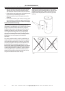
To tilt cooler forward, remove 6 screws holding the
cooler in place. While removing the last screw,
hold the top of the cooler in place to prevent the
cooler from tilting. Once the screw is removed,
allow the cooler to tilt forward until the pivot
brackets touch the pivot stops. The cooler will stop
tilting at 45 degrees.
Cover the main drive motor with plastic sheeting to
prevent cleaning solution from entering the motor.
Before cleaning coolers, check to ensure aftercooler
intake and discharge holes are plugged to prevent
contamination of compressor system. Clean coolers
with a mild cleaning solution.
WARNING
Strong cleaners can harm aluminium cooler parts.
Follow cleaner manufacturers instructions for use.
Wear appropriate safety equipment.
After cleaning is complete, reassemble in reverse
order.
N125/200H (N90/160K) SINGLE STAGE and N100/200H
(N75K−160K) TWO STAGE
The coolers in these machines can either be cleaned by
removing the complete cooler for off site cleaning or
’back flushing’ in place using a high pressure hose and
gaining access through the holes in the intermediate
plenum.
•
•
•
•
•
•
•
•
•
•
•
•
Instructions for cleaning the coolers while installed in
the compressor.
While cleaning coolers, great care must be taken to
protect the rest of the machine from moisture and
contamination by covering sensitive parts with plastic
sheeting.
Remove 4 screws from enclosure panel below
moisture separator and remove panel.
Remove 4 screws from enclosure panel above
moisture separator and remove panel.
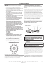
Remove the 16 screws securing the access panels on
the cooling plenum and remove covers.
Cover main drive motor, PDM Heat sink blower
motor, drain valve, and cooling motor variable speed
drive with plastic sheeting to prevent damage from
entrance of cleaning solution.
Cover inlet of blower wheel with plastic sheeting to
prevent entrance of cleaning fluid.
Cover the inlet grill of the intake panel with plastic
sheeting to prevent cleaning solution from exiting
the compressor.
Attach drain hose to the coupling on the bottom of
the plenum to allow the cleaning solution to drain
outside the compressor. Alternately, place large
bucket underneath plenum to collect cleaning fluid.
Use an extended length nozzle and a mild cleaning
solution to clean the coolers.
WARNING
Strong cleaners can harm aluminium cooler parts.
Follow cleaner manufacturers instructions for use.
Wear appropriate safety equipment.
Cleaning fluid will collect on both sides of the cooler
core. If required, periodically drain fluid from intake
plenum and bucket to prevent them from over
flowing.
After cleaning is complete, dry off plenum, intake,
and cooler core. Reassemble parts in reverse order.
If the cooler cores are unable to be cleaned while in-
stalled in the compressor, remove cooler as follows:
Remove 5 screws from panel below the intake panel
and remove panel. Be careful not to damage the
electrical leads entering the panel.
Remove 8 screws from the intake panel and remove
panel.
Remove 8 screws from the intake plenum supports
and remove the supports.
Remove the 10 screws securing the intake plenum
and remove the plenum
Disconnect both oil lines and both air lines from the
cooler. Plug all 4 inlets to prevent cleaning fluid from
entering the cooler cores.
•
•
•
•
•
•
•
•
•
•
•
•
•
•
•