


IRN37 - 160K - CC & IRN50 - 200H & IRN75 - 160K - 2S & IRN - 100 - 200H - 2S & IRN 250 - 300H - 2S
http://air.irco.com
83
10.0 MAINTENANCE
10.4 ROUTINE MAINTENANCE
This section refers to the various components which
require periodic maintenance and replacement.
For all other maintenance, contact your local Ingersoll
Rand office, Distributor or Air Center.
Refer to safety information and maintenance procedures
prior to carrying out any of the maintenance in the
following sections.
Prior to starting
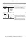
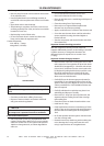
Coolant level checking procedure
The coolant level should be checked daily. A coolant level
sight glass is located on the side of the separator tank
and while the machine is running on load, coolant should
always be visible in the sight glass. The normal position is
half way.
Stop the machine and ensure coolant is still visible in the
sight glass.
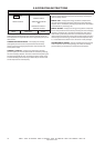
Adding coolant
Run the compressor for a minimum of 40 seconds, the
coolant level should be visible in the sight glass. If not,
stop the compressor, depressurize by isolating the
compressor from the system, pressing the emergency
stop to vent the separator tank & airend & then slowly
unscrew the coolant fill plug to verify all pressure has
been released and add coolant. Replace the coolant fill
plug, restart the compressor and recheck the coolant
level. Repeat until the coolant level is visible in the sight
glass with the compressor both running and stopped.
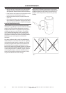
Do not add coolant through the intake of the compressor,
as this can result in overfilling, saturation of the separator
filter element, and coolant carry−over downstream.
DANGER
Under no circumstance should the compressor be
operated with the coolant fill plug removed.
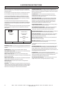
Coolant change procedure
WARNING
The coolant filter and coolant may be hot!
The compressor features a ’no drip’ coolant drain feature
which requires no special tools and minimizes the risk of
coolant spillage.
It is better to drain the coolant immediately after the
compressor has been operating as the liquid will drain
faster and any contaminant will still be in suspension
Remove the cap from the drain valve located at the
front of the separator vessel.
Place a suitable container close to the drain valve.
Screw the coolant drain hose onto the drain valve.
As the threads engage, the valve will automatically
open and the coolant will drain.
Remove the drain hose. The valve will automatically
close and seal.
Replace the cap on the drain valve.
For a complete drain, remove the plug near the
vessel inlet flange and replace when complete.
Replace the coolant filter element.
Refill with correct quantity of coolant.
See 8.0 General Information.
•
•
•
•
•
•
•
•