


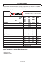
IRN37 - 160K - CC & IRN50 - 200H -CC & IRN75 - 160K - 2S & IRN100 - 200H - 2S & IRN 250 - 300H - 2S
http://air.irco.com
84
10.0 MAINTENANCE
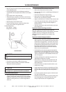
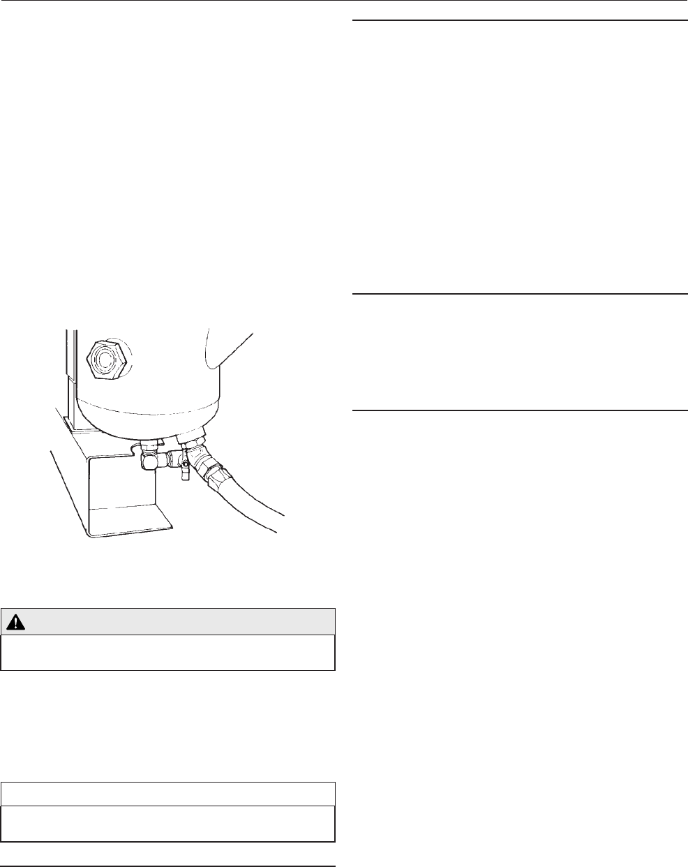
Drain sequence for N250/300H−2S
Remove plug from drain valve located on the bottom
of the separator tank.
Install supplied drain hose and fitting assembly in
end of drain valve and place end of hose in a suitable
pan.
Open drain valve to start drainage.
After draining is complete, close valve, remove hose
an fitting assembly from valve, and store in a suitable
location for future use.
Replace plug in end of drain valve.
Do not store drain hose in starter box after it has
been used to drain the separator tank.
Coolant fill quantity
250−300 hp − 2 stage
40.0 gallons (152 liters)
COOLANT DRAIN
CAUTION
Do not mix coolant types. Use only coolant specified
by IR
Start the compressor and check for leaks.
Check the coolant level, refilling if necessary.
Dispose of waste coolant in accordance with local
and governmental regulations.
NOTICE
Shorter coolant drain intervals may be necessary if
the compressor is operated in adverse conditions.
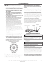
Food Grade Coolant option
SSR Food Grade Coolant is a polyalphaolefin base
coolant. Change after 1000 hours or every 6 months
whichever comes first. Do not operate unit past this
1000 hour change interval, as coolant degradation
will occur.
•
•
•
•
•
•
•
•
•
•
Coolant filter change procedure
Loosen filter element with the correct tool.
Remove the element from the housing.
Place the old element in a sealed bag and dispose of
in a safe way.
Clean the mating face of the housing.
Remove the new Ingersoll Rand replacement
element from its protective package.
Apply a small amount of coolant to the element seal.
Screw the new element down until the seal makes
contact with the housing, then hand tighten a
further half turn.
Start the compressor and check for leaks and check
the coolant level.
Separator element checking procedure
With the compressor running on load, check the
separator differential pressure via the Intellisys controller.
It will be necessary to change the element if the
differential pressure equals zero or exceeds 1 bar
(12 psig).
Separator element change procedure
Remove all the capscrews securing the cover to the
tank except the screw opposite the pivot bolt which
should be left engaged by 2−3 threads with at least
6.5mm (0.25”) clearance from the screw head to the
lid. Rotate the jacking bolt clockwise until the cover
lifts off the tank at least 2mm (0.08”) all the way
around the tank. The cover can now be rotated to
allow access to inside the tank.
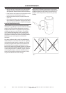
Carefully lift out the element spacer and retain for
reassembly. Do not damage the flat surfaces of the
spacer as this may cause higher oil carryover or leaks.
A hoist is available for 175HP (90kW) machines and
above if required.
Carefully withdraw the used element, place it in a
sealed bag and dispose of it safely.
Remove the O−rings from the top of the tank, the
separator element sealing face and the scavenge
tube sealing face.
Clean the surfaces on both the tank and the cover.
Install new O−rings
Install replacement element remembering to fit the
small O−ring on the scavenge tube and positioning
the tube into the matching hole in the Separator
Tank
Re−fit the separator element spacer with the notch
over the scavenge tube.
Rotate the tank cover back into position taking care
not to damage the O−ring, and locate the cover
using 2 capscrews but do not tighten down.
•
•
•
•
•
•
•
•
•
•
•
•
•
•
•
•
•