


IRN37 - 160K - CC & IRN50 - 200H & IRN75 - 160K - 2S & IRN - 100 - 200H - 2S & IRN 250 - 300H - 2S
http://air.irco.com
23
7.0 INSTALLATION
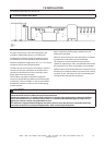
7.4 WATERCOOLED UNITS
Cooling Water Piping
Water piping to and from the compressor package must
be 1”diameter or larger for N37/75K (N50/100H), 11/2”
diameter or larger for N75/160K (N100H/200H) and 2.0”
diameter or larger for N250/300H−2S. Isolation valves
with side drains should be installed on both the inlet and
outlet lines. Also a strainer of 2mm−mesh size should
be installed on the inlet line. Strainers are available from
Ingersoll Rand. Ingersoll Rand CPN 54689997 (N37/45K &
N50/60H) or CPN 54690029 (N55/75K & N75/100H)
A normally closed solenoid valve is fitted to the water
outlet side of the compressor package. This is wired
into the compressor control circuit and closes when the
compressor stops.
Carefully inspect your water system before installing
the compressor package. Ensure that the piping is free
of scale and deposits that may restrict water flow to the
compressor package.
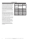
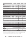
Proper operation of your compressor requires that the
water flow listed below be provided at a maximum supply
temperature of 46° C (115° F).
Model
Range
Minimum cooling water requirement vs
water inlet temperatures, in litres per
minute (US gallons per minute)
10°F /
50°F
21°F /
70°F
32°C /
90°F
46°C /
115°F
N37 23(6.0) 23 (6.0) 38 (10.0) 57(15.0)
N45 27(7.0) 30(8.0) 49(13.0) 76(20.0)
N55 51(13.5) 46(12.0) 38(10.0) 38(10.0)
N75 95(25.0) 68(18.0) 46(12.0) 53(14.0)
N75-2S 175(46.0) 133(35.0) 106(28.0) 76(20.0)
N90 84(22.0) 72(19.0) 65(17.0) 72(19.0)
N110 95(25.0) 80(21.0) 72(19.0) 87(23.0)
N132 110(29.0) 91(24.0) 87(23.0) 106(28.0)
N160 125(33.0) 118(31.0) 106(28.0) 125(33.0)
N250 91(24.0) 110(29.0) 179(47.0)
N300 95(25.0) 133(35.0) 220(58.0)
Water temperature and pressure gauges should be
installed in the water piping for use in any fault finding
of the water system. Water pressure should ideally be
between 3 and 5 bar (43.5 and 72.5 psi) but must not be
above 10 Bar (145 psi)
Water cleanliness is also extremely important. Cleaning of
coolers as a result of fouling is a customer responsibility.
Therefore, it is highly recommended that proper water
quality must meet the requirements listed in WATER
QUALITY RECOMMENDATIONS later in this section.
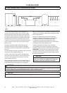
Venting the water system
At the initial installation or for start−up after draining the
water system proceed to vent the system as follows.
Locate the water system vent cocks on top of the
aftercooler and lubricant cooler.
Open the water valve(s) allowing water to flow to the
package.
Open the vent cocks and allow all air to escape from
the system. When water is observed at the vent
cocks, close them.
The system is now vented.
Draining the water system
Should it become necessary to completely drain the
water system, proceed as follows.
Disconnect the inlet and discharge water lines from
the connections located at the rear of the unit.
Locate the aftercooler and lubricant cooler. Remove
the drain plugs located at the bottom of the coolers.
Allow the system to completely drain.
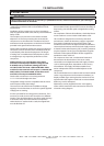
N75−160k, N100−200H Watercooled
See piping and instrumentation diagram (Section
8.3). The coolers are piped in a ”parallel” water flow
arrangement with a manual trim valve controlling the
flow through the aftercooler. An additional automatic
anti−condensation thermal valve controls the flow of
water to the oilcooler. It has a sensor in the separator
tank and capillary to signal the valve to open and close in
order to avoid water condensing in the tank.
Adjusting the Aftercooler Trim Valve
The anti−condensation valve has no adjustment. The
Aftercooler Trim Valve is factory set and should not need
adjusting but if disturbed use following procedure.
Close valve fully clockwise and then open 1/4 turn. With
machine running loaded observe the package discharge
temperature Intellisys display. It should be be approx 15°
F (8° C) above the water inlet temperature. If it is higher,
open the valve a little more. Put a ’Warning − Do Not
Adjust’ label on the valve or fit a lock.
1.
2.
3.
1.
2.