


14
MAINTENANCE SECTION
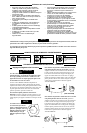
Always wear eye protection when operating or
performing maintenance on this tool
Always turn off the air supply and disconnect the air
supply hose before installing, removing or adjusting
any accessory on this tool or before performing any
maintenance on this tool.
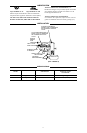
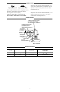
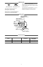
Lubrication
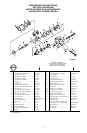
Each time a Model 232TGSLImpact Wrench is
disassembled for maintenance and repair or
replacement of parts, lubricate the tool as follows:
1. Work approximately 6 to 8 cc ofIngersoll--Rand No.
100 Greaseinto the impact mechanism. Coat the
Anvil (40) lightly with grease around the Hammer
Case Bushing (36). Inject approximately 1 to 2cc of
grease into the Grease Fitting (16).
2. Use Ingersoll--Ra nd No. 50 Oil for lubricating the
motor. Inject approximately 1to 2 air inlet before
attaching the air hose.
Disassembly
General Instructions
1. Do not disassemble the tool any further than
necessary to replace or repair damaged
2. Whenever grasping a tool or part in a vise, always use
leather--covered or copper--covered vise jaws to
protect the surface of the part or tool and help prevent
distortion. This is particularly true of threaded
members and housings.
3. Do not remove any part which is a press fit in or on a
subassembly unless the removal
4. Do not disassemble the tool unless you have a
complete set ofnew gasketsand O--ringsreplacement.
Disassembly of the Impact Wrench
1. Clamp handle of Impact Wrenchin a visewith square
driver upward.
2. Unscrew and remove the three Hammer Case Cap
Screws (38).
3. While lightly tapping on end of Anvil (40) with a
plastic hammer, lift off HammerCase (35), Hammer
Case Pilot (35B) and Hammer Case Gasket (35A).
4. Grasp Hammer Frame (30) andcarefully lift offentire
impact mechanism, making certainnot to drop two
Hammer Pins(31). If itis necessary to disassemble
the impact mechanism, refer to Disassembly of the
Impact Mechanism. If itis unnecessaryto
disassemble impact mechanism. set it aside intact.
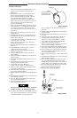
Disassembly of the Impact Mechanism
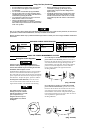
1. Set mechanism, driver end up, on aworkbench.
Note the twin hammers within the Hammer
Frame. These are identical, but mustbe placedin
the Hammer Frame ina certain relationship. Using
afelt--tippedpen,markthetophammer“T↑”and
the bottom hammer “B↑” with the arrows pointing
upward. Mark both Hammers on the same end.
2. With mechanism sittingupright on workbench, slowly
rotate Anvil ina clockwise directionuntil it comesup
solid.
If you continue to rotate the Anvil,it will cam the
Hammers out of engagement. Do not allowthis to
happen; merely rotate the Anvil until it comes up
solid.
3. Hold Hammer Frame firmly and without disturbing
the hammers, gentlylift Anvil simultaneouslyrotating
it clockwise about 1/8 of a turn from the Hammer
Frame.
The twin hammers are now free to slide fromthe
Hammer Frame when the Hammer Pins are
removed. Do not drop the Hammers (33).
4. With Anvil removed, lift out the two Hammer Pins.
5. Remove the Hammers.
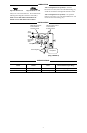
Disassembly of the Motor
1. Lift Rear Hammer Frame Washer (32)and two Motor
Clamp Washers (29) fromfront of motor.
2. Grasp splined end of Rotor (18) and pull assembled
motor from Motor Housing (1).
3. Lift Front End Plate (26) and Front Rotor Bearing
(20) from splined end ofthe Rotor.
4. Remove Cylinder (22) andVanes (25).
5. Remove Rear Rotor Bearing Retainer (21).
6. Lift Rear EndPlate (27)and Rear Rotor Bearing (19)
from Rotor.
7. Unscrew Air Strainer (6) and remove it.
8. Withdraw Throttle Valve Spring(4), Throttle Valve
(2), and Throttle Valve Stem (5). Remove Throttle
Valve Face(3) from Throttle Valve.
9. Remove Trigger Pin (8) and Trigger (7).
10. Unscrew Reverse Valve Knob Screw (15) and remove
Reverse Valve Knob (14).
ThisScrew isinstalledwith a quality
thread--locking compound. You may have to heat it
slightly toloosen the Screw.
11. While slowly rotating Reverse Valve (11), withdrawit
from Reverse Valve Bushing (9).
Be careful not tolose the Reverse Valve Detent Ball
(12) and Spring (13) from the hole in the side of the
Reverse Valve.
Assembly
General Instructions
1. Always press on the inner ring of a ball--type bearing
when installingthe bearing on
2. Always press on the outer ring ofa ball--type bearing
when installingthe bearing in
3. Whenever grasping a tool orpart in a vise, always use
leather--covered or
4. Always cleanevery partand wipe every part witha
thin filmof oil before
5. Apply a film of o--ring lubricant to all O--rings before
final assembly.
6. Check every bearing for roughness. If an open
bearing must be cleaned, wash it thoroughly in
solvent and dry it with a clean cloth. Sealed or
shielded bearings should never be cleaned.