


15
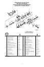
Maintenance Section (Continued)
Assembly of the Motor
1. Make certain Reverse Valve Bushing Seals (10)are
properly located in undercuts in Reverse Valve
Bushing (9).
2. Dampen Reverse Valve (11) with light oil. Install
Reverse Valve Detent Spring (13) followed by
Reverse Valve Detent Ball (12) in hole in Reverse
Valve. With the ImpactWrenchin an upright
horizontalposition andwhile facinghandle end of
Impact Wrench, slowly rotate the Reverse Valve and
insert itfrom left toright in the splined endof
Reverse Valve Bushing.
3. Apply a quality thread--locking compound toReverse
Valve Knob Screw (15). Attach Reverse Valve Knob
(14) to Reverse Valve with Reverse Valve Knob
ScrewandtightenScrewto40to50in--lb(4.5to5.6
Nm) torque.
4. Place Trigger (7) in Housing (1) and secure it with
Trigger Pin (8).
5. Install Throttle Valve Face (3)on Throttle Valve (2).
6. Install Throttle Valve Stem (5), ThrottleValve and
Throttle Valve Spring(4).
7. Install AirStrainer Assembly(6) and tighten itto 30
to 35 ft--lb (40.5 to 47.5 Nm)
8. Using a sleeve that will contact only outer ring of
bearing, press Front Rotor
9. Slip Front End Plate and Bearing over splined hub of
Rotor (18).
10. Grasp splined hub ofRotor in leather--covered or
copper--covered vise jaws so that
11. Dampen each Vane (25)with light oil and insert a
Vane intoeach vane slot.
12. Set the Cylinder (22) over the Rotor and onto the
Front End Plate.
13. Slide Rear End Plate and Bearing onto rotor hub and
against Cylinder.
14. Install Rear Rotor Bearing Retai ner (21) in groove on
rotor hub.
15. Align dowel hole in both End Plates with the one
through Cylinder and insert a guide
16. Grasp handle of the Motor Housing in
leather--covered or copper--covered vise jaws so
17. Wipe a thin film of light grease on End Plate Gasket
(28) and press Gasket firmly
18. Insert protruding end of guide rodinto dowel hole in
bore of Motor Housing and slide
19. Remove guide rodand replace it with Cylinder Dowel
(23).
20. RepositionMotor Housingin vise so that open face of
Motor Housing isupward.
21. Place two Motor Clamp Washers (29),convex side
first, against Front End Plate so
22. Place Rear Hammer Frame Washer (32) over hub of
Rotor and against Front Rotor.
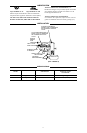
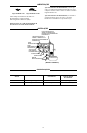
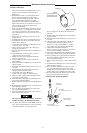
Forproperperformance,theCylinder(22)mustbe
installed according tothe following instructions:
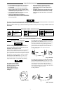
23. One endof the Cylinder hasa small dimple on the air
inlet. The end with the dimple on it must be installed
on the Front End Plate. See Dwg. TPA1778.
DIMPLE
(THISSIDEMUSTBE
INSTALLEDONTHE
FRONT ENDPLATE)
CYLINDER
(Dwg. TPA1778)
Set the Cylinder over the Rotor and onto the Front
End Plate.
24. Slide Rear End Plate and Bearing onto rotor hub and
against Cylinder.
25. Install Rear Rotor Bearing Retai ner (21) in groove on
rotor hub.
26. Align dowel hole in both End Plates with the one
through Cylinder, and insert a guide rod 5/32”
diameter x6” long (3.9 mm diameter x152 mm
long). Allow rod to protrude from Rear End Plate.
27. Grasp handle of the Motor Housing in
leather--covered or copper--covered vise jaws sothat
bore of the Motor Housing is horizontal.
28. Wipe a thin film of light grease on End Plate Gasket
(28) and pressGasket firmlyagainst RearEnd Plate.
29. Insert protruding end of guide rodinto dowel hole in
bore of Motor Housing and slide motor along rod
until it iscompletely seated.
30. Remove guide rodand replace it with Cylinder Dowel
(23).
31. RepositionMotor Housingin vise so that open face of
Motor Housing isupward.
32. Place two Motor Clamp Washers (29),convex side
first, against Front End Plate so thatinner rim of
leading Washer contactsEnd Plate, and outer rimof
trailing Washer contactsHammer Case Pilot (35B).
33. Place Rear Hammer Frame Washer (32) over hub of
Rotor and against Front Rotor Bearing.
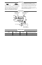
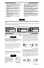
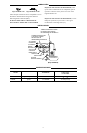
TOPHAMMER
WIDEBEVELUP
TOPHAMMER
HALF--ROUNDNOTCHONRIGHT
BOTTOMHAMMER
WIDEBEVELDOWN
BOTTOMHAMMER
HALF--ROUNDNOTCHONLEFT
(Dwg. TPD652)
A
ssembly o
f
the Impact Mechanism