


2
Using The Tool (Continued)
• Do notmodify thetool,safety devices,or accessories.
• Do notuse this toolfor purposes other thanthose
recommended.
• Use accessoriesrecommendedby Ingersoll--Rand.
• Note theposition ofthe reversing mechanismbefore
operating thetool so asto beaware ofthe directionof
rotation when operating thethrottle.
• Use onlyimpact socketsand accessories. Donot use
hand(chrome)socketsor accessories.
• WhenevertheRatchetHead is installedor
repositioned, theThrottle Lever must bepositioned so
that r eaction tor quewill nottend to retain thethrottle
in the “ON”position.
• Ratchet Wrenches arenot torque wrenches.
Connections r equiring specific torque mustbe
checked witha torque meter after f ittingwith an
impactwrench.
• Periodicallycheck thedrive endof the toolto make
certainthatthe socketretainerfunctionscorrectly,
andthat sockets and drive endsare notexcessively
wornwhich mayallow thesocket to comeoff when
rotating.
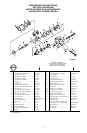
The use of other than genuine Ingersoll--Rand replacement parts may result in safety hazards, decreased tool
performance, andincreased maintenance, andmay invalidate all warranties.
Repai r s should be made o nl y by author i z e d tr ai ne d per so nne l . Co nsul t your ne a rest Inger so l l--Rand Autho r i z e d
Servicenter.
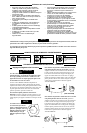
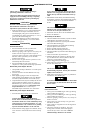
WARNING SYMBOL IDENTIFICATION
Alwaysweareyeprotection
whenoperatingor
performingmaintenance
onthistool.
WARNING
WARNING
Alwayswearhearing
protectionwhenoperating
thistool.
Readthismanualbefore
operatingtool.
WARNING
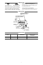
USING THE POWER MANAGEMENT SYSTEM
SettingThe Power Regulator
Impact wrenches are nottorquecontrol devices.
Fasteners with specific torque requirements must be
checkedwith suitable torque measuring devices after
installationwith animpact wrench.
232TGSL Impact Wrench incorporates a power regulator
into the reverse mechanism thatallows the operator to
have either full power output in one direction and reduced
power output in the other direction or full power output in
both directions. Toadjust the power,proceed as follows:
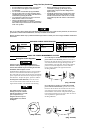
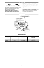
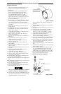
For full power in both directions, rotate the reverse
valve until the notch on eachend of thereverse valve
aligns with the number5 on each side ofthe housing.
The numbers 0 thru 5 on the
housingare onlyfor reference
and DO NOT denote a specific
power output. Zero (0)
designates the lowest power
output while five (5) denotes
the highest.
For reducedpower inthe forward direction andfull
power in the reverse direction, push the reverse valve
inward on the right side ofthe tool and rotate the reverse
valve until the notch on the right side aligns with the
desired number on the right side. This provides reduced
power in forward but full power in reverse when the
reverse valve is pushed in the opposite direction.
See Dwg. TPD1248.
(Dwg. TPD1248)
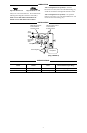
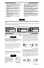
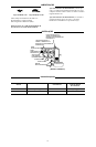
For reducedpower inthe reverse direction and full
power in the forward direction, push the reverse valve
inward on the left side of the tool androtate the reverse
valve until the notch on the left side alignswith the
desired number on the left side. This provides full power
in forward but reduced power inreverse when the reverse
valve is pushed the opposite direction.
See Dwg. TPD1249.
(Dwg. TPD1247)
(Dwg. TPD1249)