


10
This machine must be grounded. In the event of
a malfunction or breakdown, grounding provides
a path of least resistance for electric current to
reduce the risk of electric shock.
Improper connection of the equipment-
grounding conductor can result in a risk of
electric shock. The conductor, with insulation
having an outer surface that is green with or
without yellow stripes, is the equipment-
grounding conductor. If repair or replacement of
the electric cord or plug is necessary, do not
connect the equipment-grounding conductor to a
live terminal.
Check with a qualified electrician or service
personnel if the grounding instructions are not
completely understood, or if in doubt as to
whether the tool is properly grounded. Use only
three wire extension cords that have three-prong
grounding plugs and three-pole receptacles that
accept the tool’s plug.
The Mortiser is factory wired for 230 volt. You
may either install a plug or “hard-wire” the
machine directly to a control panel.
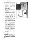
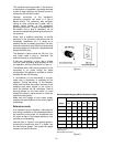
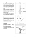
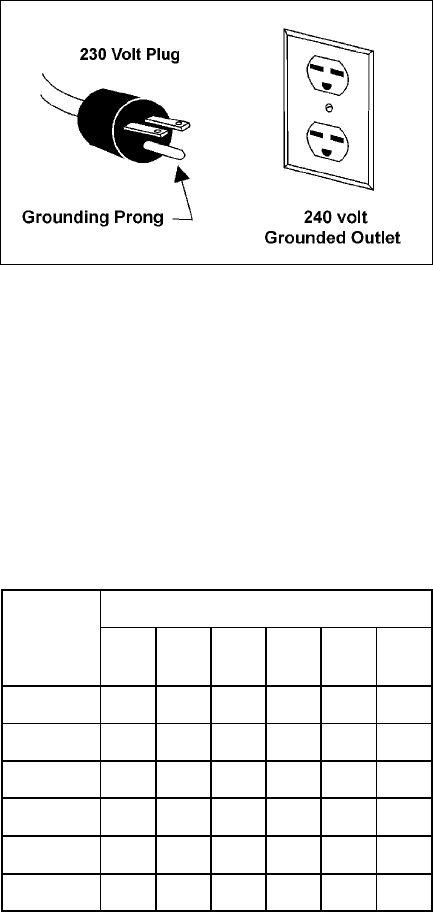
If you are connecting a plug, use a proper
UL/CSA listed grounding plug suitable for 230
volt operation, similar to that shown in Figure 4.
The Mortiser with a 230 volt plug should only be
connected to an outlet having the same
configuration. No adapter is available or should
be used with the 230 volt plug.
If the Mortiser is to be hard-wired to a panel,
make sure a disconnect is available for the
operator. During hard-wiring of the Mortiser,
make sure the fuses have been removed or the
breakers have been tripped in the circuit to
which the Mortiser will be connected. Place a
warning placard on the fuse holder or circuit
breaker to prevent it being turned on while the
machine is being wired.
Make sure the voltage of your power supply
matches the specifications on the motor plate of
the Mortiser.
Extension cords
If an extension cord is necessary, make sure the
cord rating is suitable for the amperage listed on
the machine’s motor plate. An undersized cord
will cause a drop in line voltage resulting in loss
of power and overheating.
Use the chart in Figure 5 as a general guide in
choosing the correct size cord. If in doubt, use
the next heavier gauge. The smaller the gauge
number, the heavier the cord.
Figure 4
Recommended Gauges (AWG) of Extension Cords
Extension Cord Length *
Amps
25
feet
50
feet
75
feet
100
feet
150
feet
200
feet
< 5 16 16 16 14 12 12
5 to 8 16 16 14 12 10 NR
8 to 12 14 14 12 10 NR NR
12 to 15 12 12 10 10 NR NR
15 to 20 10 10 10 NR NR NR
21 to 30 10 NR NR NR NR NR
*based on limiting the line voltage drop to 5V at 150% of the
rated amperes.
NR: Not Recommended.
Figure 5