


14
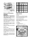
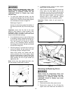
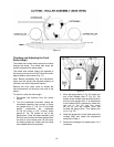
Figure 17
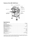
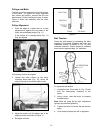
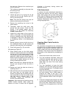
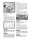
Referring to Figure 18 – if adjustment is
required:
1. Adjust the tightness of the mounting bolts
(A) and the depth of the setscrews (B) on
the extension roller frame.
Various combinations of loosening and/or
tightening of the setscrews and bolts will be
required to level the extension rollers with
the table. Adjustment is complete when the
straightedge is level with the table and all
three rollers touch the bottom of the
straightedge.
2. Adjust both front and rear extension rollers
in the same manner.
Figure 18
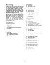
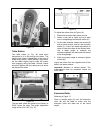
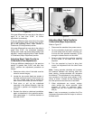
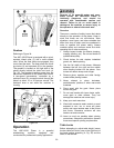
Depth of Cut Adjustment
Refer to Figure 19.
The cutting depth scale (A) is a combination
inch/metric scale with a cutting range from 0 to
6” (150mm). The distance of upward or
downward movement is controlled by the
handwheel (B). One revolution of the handwheel
is 0.158” (4mm). Before moving the head
assembly up or down, loosen the lock knobs
(C,). After obtaining the proper height for the
head assembly, tighten the lock knobs.
Note: The JWP-16OS Planer has two lock
knobs; one is located by the handwheel
(C, Fig. 19). The other is located on the opposite
(left rear) corner.
Always tighten the lock knobs before
operating the planer.
Figure 19
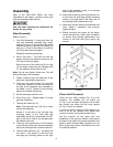
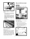
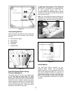
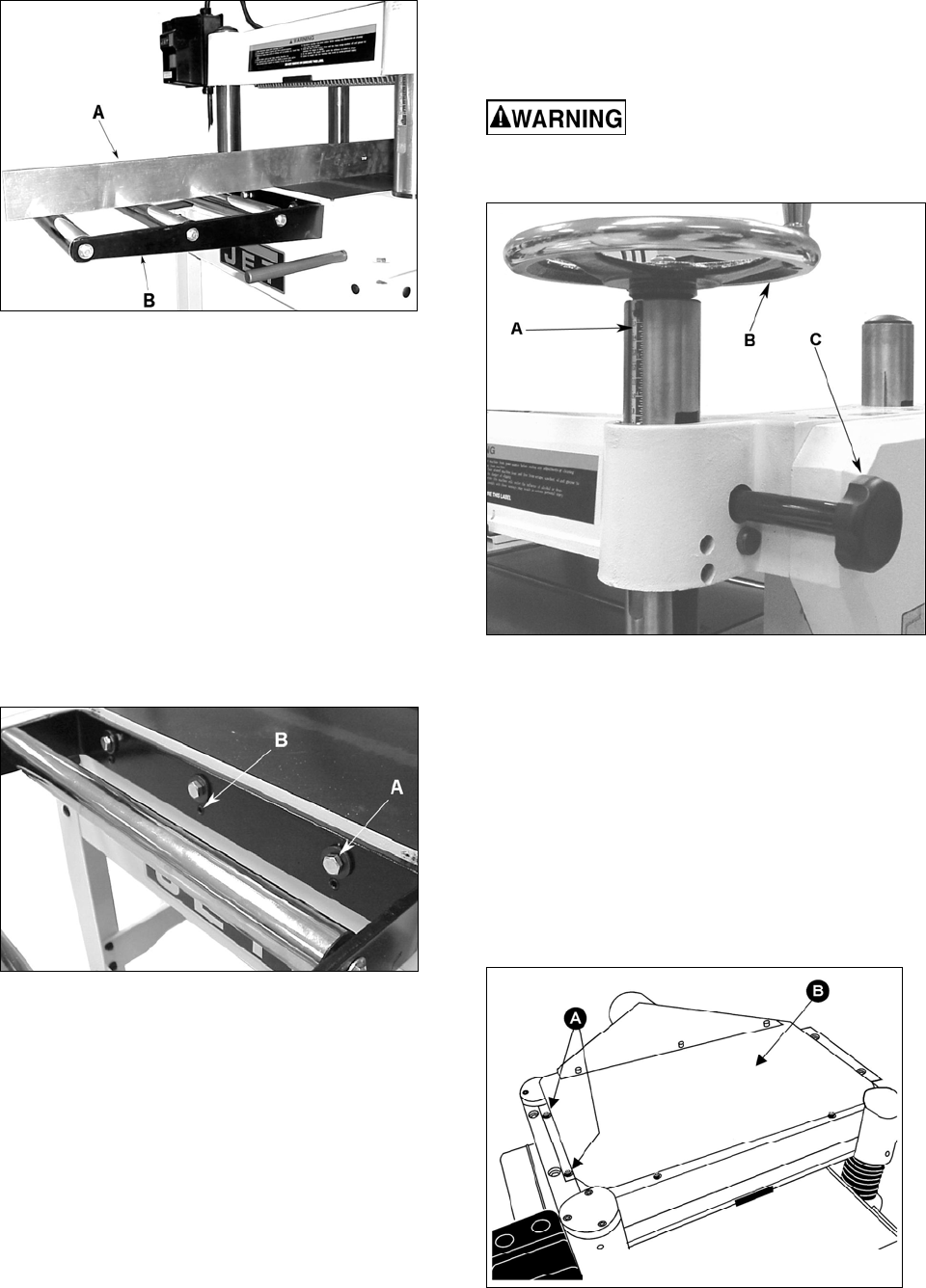
Knife Adjustment
When checking or adjusting the cutterhead
knives, proceed as follows:
1. Disconnect machine from power source.
2. Remove four hex cap screws (A, Fig. 20)
from the upper cover and three from the
bottom of the dust port. Remove the
cover/dust port (B, Fig 20) as a unit.
The cutterhead assembly can be seen from
the opening on top.
Motor assembly removed for clarity
Figure 20