


18
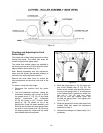
Figure 27
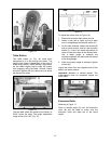
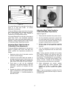
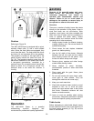
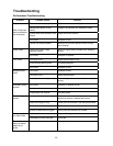
Transmitting Rollers
Figure 28 show the positions of the rollers that
are listed below and described in the following
sections.
A Anti Kickback Fingers
B Infeed Roller
C Chipbreaker
D Cutterhead
F Outfeed Roller
Figure 28
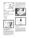
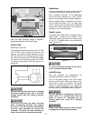
Infeed & Outfeed Roller Spring
Tension Adjustment
The infeed roller (B, Fig. 28) and outfeed roller
(F, Fig. 28) feed the stock while it is being
planed. The infeed and outfeed rollers are under
spring tension and this tension must be sufficient
to feed the stock uniformly through the planer
without slipping but should not be so tight that it
causes damage to the board and/or the rubber
coating on the outfeed roller. The tension should
be equal at both ends of each roller.
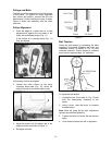
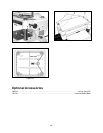
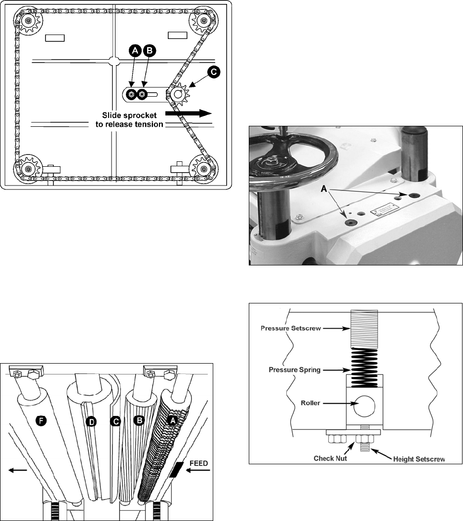
To adjust the spring tension of the infeed and
outfeed rollers, turn screws (A, Fig. 29) with a
hex wrench. A clockwise turn increases tension
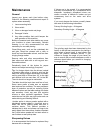
on the pressure spring (Fig. 30); a
counterclockwise turn decreases tension. Adjust
the screws at the other end of the rollers with the
same number of turns.
Note: The most effective pressure settings are
dependent on the type of lumber being planed.
Experimentation will determine the best settings.
Figure 29
Figure 30
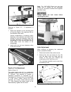
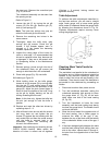
Anti-Kickback
The JWP-16OS Planer provides an anti-
kickback safety feature. The anti-kickback
fingers hang from a rod suspended across the
front of the cutterhead casting (A, Fig. 28) and
help prevent kickback of stock. It is necessary to
inspect them regularly to make sure they hang
freely. Check that they are free of gum and pitch
to insure independent movement and correct
operation.