19
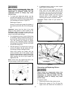
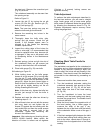
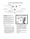
Figure 31
Checking and Adjusting the Feed
Roller Height
The infeed and outfeed rollers propel the lumber
through the planer. The rollers also press the
lumber flat against the planer table.
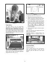
The infeed and outfeed rollers are adjusted at
the factory and are set at 0.020" below the knife-
edge at bottom dead center (Fig. 31).
Note: Before proceeding with this adjustment,
make sure the knives are adjusted properly as
outlined in the Knife Adjustment section.
Remove the drive chain cover to access the
roller adjustments on the drive chain side of the
planer.
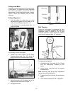
To check or verify the roller height:
1. Disconnect the machine from the power
source.
2. Turn the handwheel clockwise, raising the
cutterhead assembly high enough to place
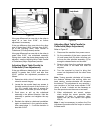
the gauge block (J, Fig. 32) on the table
directly underneath the cutterhead
(D, Fig. 32) Using a 0.02” (0.5mm) feeler
gauge (K, Fig. 32) placed on top of the
gauge block, lower the head assembly until
the knife just touches the feeler gauge when
the knife is at its lowest point. Do not move
the working table any further until the infeed
and outfeed rollers are adjusted.
Figure 32
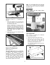
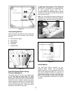
3. Move the gauge block (J, Fig. 33) under one
end of the outfeed roller (F, Fig. 33). The
bottom of the outfeed roller should just touch
the top of the gauge block. If an adjustment
to the outfeed roller is necessary, loosen the
jam nut (L, Fig 33) and turn screw
(M, Fig. 33) until the outfeed roller just
touches the gauge block. Then tighten jam
nut (L, Fig. 33).
4. Slide the gauge block to the other end of the
outfeed roller and repeat the adjustment
described in Step 3.
5. Recheck the settings and repeat steps 1-4 if
necessary.


