


9
Assembly
Most of the JWP-16OS Planer has been
assembled at the factory. However some parts
must be assembled after delivery.
Use care when cleaning the cutterhead; the
knives are very sharp.
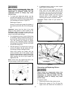
Stand Assembly
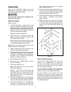
Refer to Figure 1.
1. Cast Foot Assembly – Using parts from the
cast foot assembly hardware bag, mount
casting (2) to leg (1) by inserting two socket
head flat screws (3) through the casting (2)
and leg (1). Place a flat washer (4) and hex
nut (5) on the screw and tighten.
Repeat for remaining three legs.
2. Stand Top (front) – The front and rear top
stands (braces) are identical except for the
JET logo on the front piece.
Mount one end of the stand top (6) to a leg
(1) and fasten using two each carriage bolts
(7), flat washers (8) and hex nuts (9).
Note: Do not over tighten at this time. This will
be the final step in the assembly.
3. Fasten a second leg to the other end of the
stand top, repeating the step above.
4. Take one long stand brace (10) and with
(4 ea) bolts, washers, and hex nuts fasten to
the legs of the assembly just completed in
the steps 2 and 3. Fasten to the mounting
holes in the middle of each leg.
5. Set this assembly aside for now.
6. Stand Top (rear) – Repeat steps 2–4 using
parts still remaining.
7. Take the left stand top (11)
Note: The right stand top (13) has a cutout
and will be used later.
Secure it to left side of the left legs (top
mounting holes) of the front and rear
assemblies previously constructed (the JET
logo is the front) using 4 ea carriage bolts,
flat washers and nuts.
8. Take one short stand brace (12) and secure
to the left legs of the front and rear assembly
with (4 ea) carriage bolts, washers and nuts.
9. Take the right stand top (13) – this piece has
the cutout – and secure it to the front and
rear legs (top mounting holes) on the right
side of the assembly using 4 ea carriage
bolts, washers and nuts.
10. Secure the remaining short stand brace (14)
to the front and rear legs (middle mounting
holes) on the right side of the stand with (4
ea) carriage bolts, washers and nuts.
11. Make sure that the stand is symmetrical and
level. Adjust if necessary and securely
tighten all bolts.
12. Before mounting the planer on the stand,
locate the stand on a solid, level foundation
to ensure best planing performance and
anchor to the floor with good quality lag
screws.
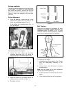
Figure 1
Planer Unit Placement
There are four lifting handles (Fig. 2) on the
machine. The handles can be pulled out
(A, Fig. 2) for use when the planer is to be lifted
and moved and slides into the body casting
(B, Fig. 2) when not needed.
If a sling or forklift is used to lift the machine, be
sure to lift by the handles only. Make sure
machine is kept in level position while lifting.
Set the machine on the stand that was
assembled in the previous section, then secure
the base to the stand using parts provided in the
base to stand hardware bag, consisting of 4 ea
M8 x 30 hex cap screws, 4 ea M8 hex nuts, and
8 ea M8 flat washers.