


16
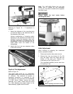
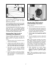
the dust port. Remove the cover/dust port
(Fig. 20) as a unit.
The cutterhead assembly can be seen from
the opening on top.
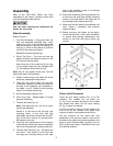
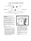
Refer to Figure 21:
3. Loosen the gib (C) by turning the six gib
screws (D) into the gib. Remove gib (C),
knife (A) and springs (E).
Note: The inner two springs may pop out
when the knife and gib are removed.
4. Remove the remaining two knives in the
same manner.
5. Thoroughly clean the knife slots, gibs,
springs and gib screws. Check the gib
screws; if the threads appear worn or
stripped or if the heads are becoming
rounded, replace them.
6. Inspect the cutting edge of the knives for
nicks or wire edge. It is recommended that
knives be replaced when they become dull
or damaged. If they are to be reused, refer
to Sharpening Knives in the Maintenance
Section.
7. Reinsert springs, knives and gib into slot of
the cutterhead. Back out gib screws just
enough to hold the knife in the cutterhead.
8. Place knife gauge (Fig. 23) over knife.
Still referring to Figure 21:
9. While holding down on the knife gauge,
loosen all six gib screws (D) by turning them
into the gib (C) until cutting edge of knife
comes into contact with the protrusion of the
gauge (B). Adjust the jack screws higher or
lower to touch the bottom of the knife. Snug
up the gib by slightly backing out the six
locking screws against the slot.
Note: At this time only, tighten the knife into
the slot just enough to hold the knife in
position.
10. Replace and reset the other two knives by
repeating steps 3 – 9.
11. After all three knives are set with the screws
just snug, back out and tighten the six
screws (D) against the slot starting with the
end screws first and then the center screws
until the knife is securely held in the
cutterhead. Tighten the remaining two
knives in the same manner.
Important: After replacing and checking knives,
CHECK AGAIN carefully. Make certain the
direction of knives is correct and all eighteen
(3 knives x 6 screws) locking screws are
tightened securely.
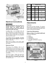
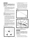
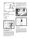
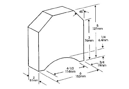
Table Adjustment
To perform the table adjustments described in
the next two sections, you will need a straight
edge, feeler gauge, and a home made gauge
block made of hardwood. Make the gauge block
by following the dimensions shown in Fig. 24.
Precision adjustments require accuracy when
milling the gauge block.
Figure 24
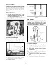
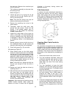
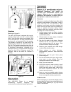
Checking Work Table Parallel to
Cutterhead
The worktable is set parallel to the cutterhead at
the factory and no further adjustment should be
needed. If your machine is planing a taper, first
check to see if the knives are set properly in the
cutterhead. Then check to see if the worktable is
set parallel to the cutterhead by proceeding as
follows:
1. Disconnect machine from power source.
2. Turn the handwheel clockwise; raising the
cutterhead assembly high enough to place
the gauge block (A, Fig. 25) on the work
table under one end of the head casting
(B, Fig. 25).
3. Turn the handwheel to lower the head
assembly until the head casting body barely
touches the gauge block. The blades should
not touch the block.
4. Slide the block toward the opposite side of
the head casting. Use a feeler gauge to
measure the width of the gap, if any,
between the top of the block and the bottom
of the cutterhead. Make a note of the gap, if
any.
5. If the block wedges tightly between the table
and the head casting when shifting from one
side to the other, repeat steps 2 through 4,
but start from the opposite end of the head
casting.