


1817
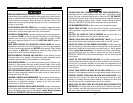
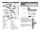
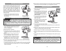
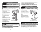
INSTALLING THE CENTER PULLEY
The head assembly contains three pulleys. The first
pulley is on the is on the spindle shaft and the third
pulley is on the motor shaft. The center pulley acts
as an idler pulley making the installation and
removal of belts easier. This pulley plays an
essential role in allowing the operator a safe way to
easily change speeds of the drill press to match the
needs for the job.
1. Install the center pulley (located in the loose
parts bag) and install it in the hole inside the
head assembly.
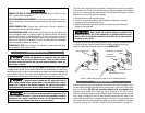
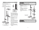
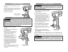
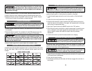
ADJUSTING THE DRIVE PULLEYS
The drive pulleys on the spindle shaft and the motor
shaft may loosen during shipment. It is crucial that these pulleys are the
same height on their respective shafts. Failure to square these pulleys could
result in premature belt wear or damage to the motor and spindle bearings
or both.
1. Lay a straightedge across the tops of the three
pulleys. If properly adjusted, they should all
touch the straightedge.
2. Adjust the pulleys if necessary.
3. To adjust the motor pulley, loosen the setscrew
that attaches the pulley to the shaft using a hex
wrench.
4. Move the pulley up or down until it is in line
with the straightedge. Tighten the setscrew.
5. If the pulley is still not in alignment, using an
adjustable wrench, loosen the four (4) bolts
holding the motor onto the column bracket.
6. Slide the motor slightly upward and retighten the bolts. Make the final adjust-
ments by repeating steps 1 through 4.
7. To adjust the spindle pulley, loosen the setscrew with a hex wrench and slightly
move the pulley upward or downward until it is in line with the straightedge.
Tighten the setscrew.
8. When finished, recheck the alignment of all three pulleys with the straightedge
ensuring they are all the same. Make any final adjustments necessary.
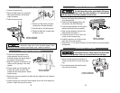
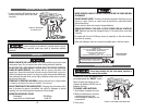
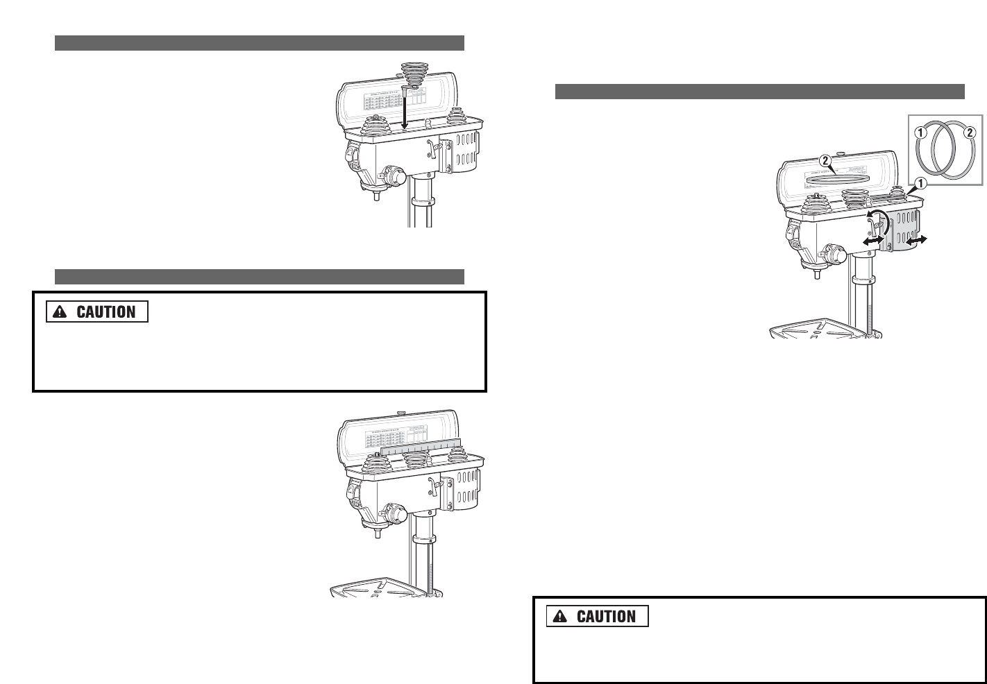
INSTALLING THE DRIVE BELTS
1. Remove the (2) two V-belts from the
loose parts bag.
2. Open the belt guard. Select the proper
belt orientation for the correct speed
for the drilling operation from the
speed chart located on the inside top
of the belt guard.
3. The longer of the two V-belts always
goes from the spindle pulley to the
center idler pulley.
4. The shorter of the two V-belts always
goes from the idler pulley to the
motor pulley. This belt is always
installed first.
5. Loosen the tension lock knob (located
on the right side of the head as you face toward the rear) in a counter-clock-
wise direction.
6. Moving the motor toward the front of the drill press, slide the shorter of the
V-belts over the idler pulley and the motor pulley.
7. Slide the longer of the V-belts over the idler pulley and the spindle pulley.
8. Move the motor towards the rear of the drill press and tighten belt tension lock
knob.
9. The V-belts should deflect about 1/2" thumb pressure at the center for proper
tension.
10.Should the drive belts slip during drilling operations, re-tension the drive belts.
Over-tensioning a drive belt may cause the motor to not
start or may cause damage to the motor bearings or the spindle bearings. If
you suspect there may be bearing damage, contact Alltrade Customer
Service at 1-800-590-3723. Do not attempt to make repairs yourself.
FIGURE 10. ADJUSTING
THE DRIVE PULLEYS
FIGURE 11. INSTALLING
THE DRIVE BELTS
FIGURE 9. INSTALLING
THE CENTER PULLEY