


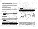
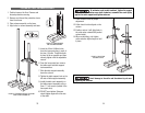
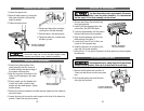
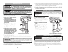

INSTALLING THE HEAD ASSEMBLY
The Head Assembly weighs approximately 55 pounds.
Use caution when lifting it onto the column assembly. It is recommended
that two people lift the head assembly onto the column.
1. Remove and discard the protective bag
from head assembly.
2. Carefully lift head assembly above the
column tube. See CAUTION above.
3. Lower the head assembly onto the column
tube and slide down as far as possible.
4. Align the head assembly with the work-
table and base. See Figure 7.
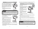
5. Locate the (2) two 10 mm X 12mm set
screws in the loose parts bag.
6. Install the setscrews in the holes on the
right side of the head assembly.
7. Using a 5mm “L” hex wrench (located in the loose parts box) securely tighten
the setscrews.
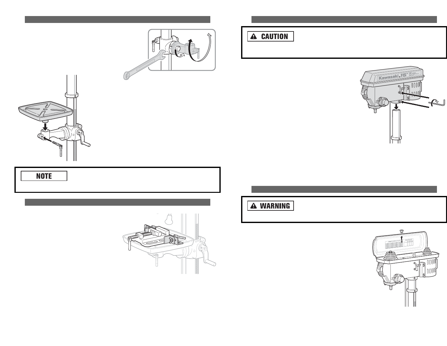
INSTALLING BELT GUARD KNOB
To avoid possible injury, always keep the belt guard closed
during drill press operation. Failure to do so could result in serous injury.
1. Remove the belt guard knob and 5mm X
12mm pan head screw from the loose parts
bag.
2. Open the belt guard and install the knob
using the hole provided.
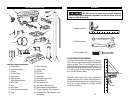
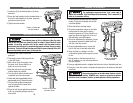
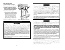
INSTALLING THE TABLE ASSEMBLY
1. Loosen the support lock.
2. Raise the table support, by turning the
table crank clockwise, until working
height is attained.
3. Tighten the support lock.
Should the table not fit into the table support freely,
carefully pry the table support open slightly using a slotted screwdriver.
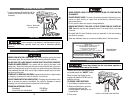
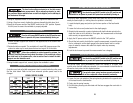
INSTALLING THE VISE ASSEMBLY
1. Place the two metal squares of the
clamp assembly into two corners of
the table and align the tapered edge of
the squares with the groves.
2. Align the long slots on the base of the
clamp over the openings in the metal
squares.
3. Place a washer over the threaded end
of each lock handle. Insert the lock
handles into the metal squares. Tighten
handles loosely.
4. Position the clamp as needed on the table and fully tighten the lock handles to
secure the clamp.
5. Loosen the wing nut to move the small support on the front of the clamp into
position. Tighten the wing nut to secure.
15 16
FIGURE 7. INSTALLING
THE HEAD ASSEMBLY
FIGURE 8. INSTALLING
THE BELT GUARD KNOB
4. Remove and discard the protective
covering from the table assembly.
5. Place the table in the table support.
6. Tighten the table lock, located under
the table, by hand.
FIGURE 5. INSTALLING
THE TABLE ASSEMBLY
FIGURE 6. INSTALLING
THE VICE ASSEMBLY