


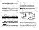
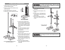
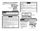
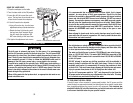


To minimize crank handle backlash, tighten the support
lock, rotate the elevation worm shaft clockwise, assemble the crank tightly
against the table support and tighten setscrew.
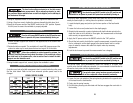
11.Check column collar for proper
adjustment.
12.Collar should not be aligned on the
column.
13.Position rack so it will slide freely in
the collar when rotated 360 (around
column table).
14.When re-adjusting, only tighten
collar setscrew tight enough to hold
it place.
Avoid damage to the collar and the column by not over-
tightening the setscrew.
1413
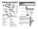
COLUMN AND TABLE HARDWARE ASSEMBLY
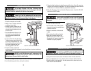
1. Position base on the floor. Remove and
discard protective covering.
2. Remove and discard the protective sleeve
from the column.
3. Place column assembly on the base.
4. Align holes in column assembly and base.
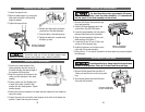
FIGURE 3. ATTACHING SUPPORT LOCK AND
TABLE CRANK ASSEMBLIES
FIGURE 2. ATTACHING BASE
AND COLUMN ASSEMBLY
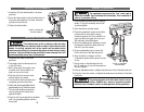
FIGURE 4. ADJUSTING
COLUMN COLLAR
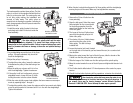
5. Insert the 10mm X 40mm bolts,
from the loose parts bag, in each of
the four (4) holes. Thread the bolts
by hand as far as possible and then
securely tighten with the adjustable
wrench.
6. From the loose parts box, remove
the table crank and table support
lock assemblies.
7. Slide the table support assembly
down the column.
8. Tighten the table support lock on the
left side of table support assembly.
9. Install the table crank assembly on
the table support assembly using a
3mm “L” hex wrench (located in the
loose parts box).
10.DO NOT over-tighten. Setscrew
should tighten against the flat area
of the shaft.