


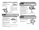
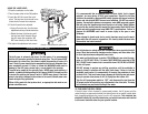

SETTING THE DRILLING DEPTH ADJUSTMENT
Turn the drill press ON/OFF switch to the OFF position and
disconnect the AC power to prevent drill press from accidentally turning on.
The drilling depth adjustment is used when more than one hole is to be drilled to
exactly the same depth (i.e. drilling holes for spindles in a handrail).
1. Locate the depth gauge and pointer (on the inner portion of the feed handle
hub).
2. Loosen the lock screw (located next to the depth gauge).
3. Rotate the hub assembly counter clockwise until depth indicator points to the
depth the holes are to be drilled to. Once again, the measurements on the depth
scale are only an approximate value.
4. Apply the AC power and turn the ON/OFF switch to the “ON” position.
5. Should the hole need to be drilled to a specific measurement, as possibly speci-
fied on a blueprint, set the depth gauge to the desired depth, test on a scrap
piece of material, measure the actual hole depth, make any necessary
adjustments.
6. Lock the lock screw to prevent the measurements from changing.
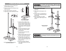
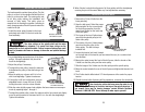
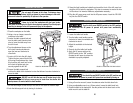
ADJUSTING THE SPINDLE RETURN SPRING
Turn the drill press ON/OFF switch to the OFF position and
disconnect the AC power to prevent drill press from accidentally turning on.
The spindle return spring automatically returns the spindle to its upper most
position when the feed handles are released. It is recommended the feed handles be
allowed to slowly return to their highest position.
The spindle return spring has been properly adjusted at
the factory and should not be re-adjusted unless absolutely necessary.
1. Loosen the two nuts outside of the spring housing located on the opposite side
of the head from the feed handles.
2. Firmly grip the spring housing.
3. Pull the spring housing out and rotate until the boss engages the next notch in
the housing.
28
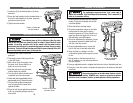
The bevel scale settings and pointer on the table mount
are only an approximate measurement. Use a magnetic protractor (or simi-
lar precision device available from a retail tool supplier) on the tabletop to
set the desired tilt angle.
4. Using an adjustable wrench or a 24mm socket, tighten the table bevel lock.
5. Using a 3mm hex wrench, tighten the setscrew beneath the table bevel lock.
6. Apply the AC power and turn the ON/OFF switch to the “ON” position. Operate
the drill press to ensure the worktable is properly adjusted.
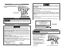
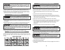
ROTATING THE WORKTABLE
Turn the drill press ON/OFF switch to the OFF position and
disconnect the AC power to prevent drill press from accidentally turning on.
1. Loosen the table support lock located on the opposite side of the column than
the worktable.
2. Rotate the table as needed. The worktable will rotate 360 (degrees around the
column to make way for work pieces that are too large to fit on the table.
When the worktable is rotated around the column, the
elevation rack should move freely about the column. If the rack binds or does
not slide freely in the column collar, refer to section 0 and re-install the table
support arm and elevation rack.
3. Using the table support lock, securely tighten the worktable in place.
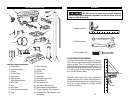
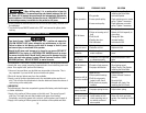
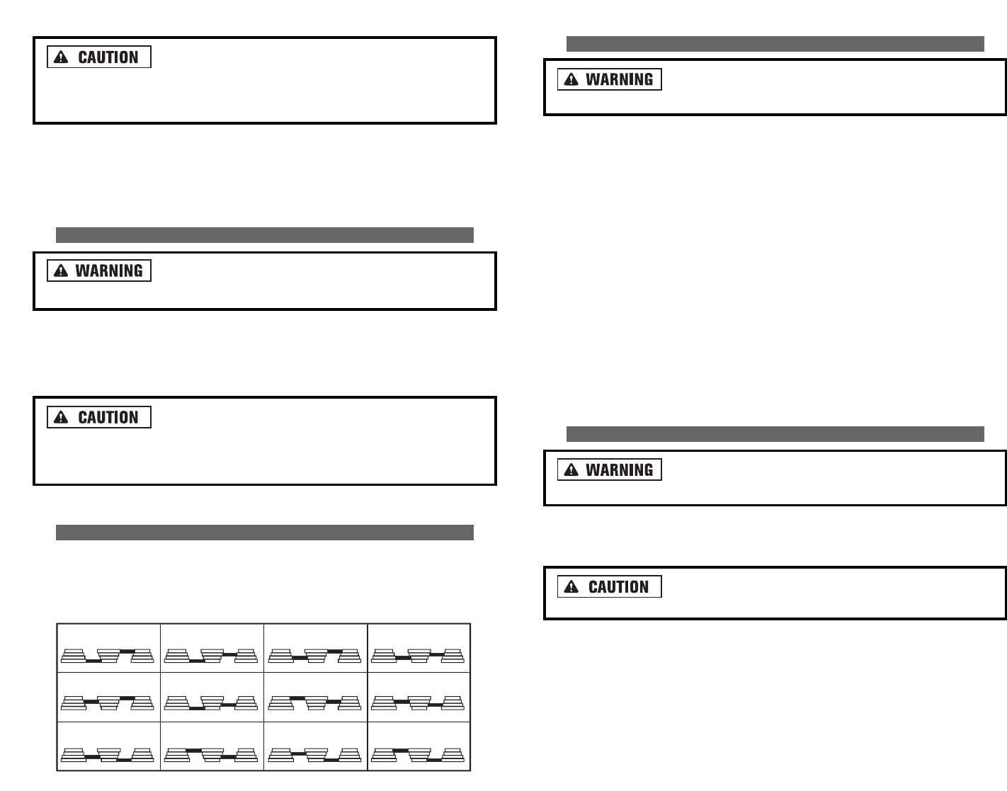
ADJUSTING THE DRILL PRESS SPINDLE SPEED
A spindle speed and pulley/belt arrangement chart is posted inside the pulley cover.
See the chart below. Refer to this chart whenever spindle speeds need to be
changed.
250 340 390 510
600 650 990 1550
1620 1900 2620 3100
SPINDLE SPEEDS IN RPM