


#$&(#"
&#"(&# The ARC CONTROL dial is active in
the CV-WIRE, CC-STICK and DOWNHILL PIPE modes,
and has different functions in these modes. This control is
not active in the TIG and ARC GOUGING mode.
'(<>34 In this mode, the ARC CONTROL dial
sets the short circuit current (arc-force) during stick welding
to adjust for a soft or crisp arc. Increasing the dial from –10
(soft) to +10 (crisp) increases the short circuit current and
prevents sticking of the electrode to the plate while welding.
This can also increase spatter. It is recommended that the
ARC CONTROL be set to the minimum number without
electrode sticking. Start with a setting at 0.
#+" $$<>34 In this mode, the ARC CONTROL
dial sets the short circuit current (arc-force) during stick
welding to adjust for a soft or a more forceful digging arc
(crisp). Increasing the number from –10 (soft) to +10 (crisp)
increases the short circuit current which results in a more
forceful digging arc. Typically a forceful digging arc is pre-
ferred for root and hot passes. A softer arc is preferred for fill
and cap passes where weld puddle control and deposition
("stacking" of iron) are key to fast travel speeds. It is recom-
mended that the ARC CONTROL be set initially at 0.
*+&<>34 In this mode, turning the ARC CONTROL
clock wise from –10 (soft) to +10 (crisp) changes the arc
from soft and washed-in to crisp and narrow. It acts as an
inductance/pinch control. The proper setting depends on the
procedure and operator preference. Start with a setting of 0.
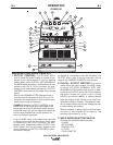
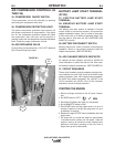
+ #)($)( (&!" ' +( "
")(Provides a connection point for the electrode and
work cables.
&#)" '() Provides a connection point for
connecting the machine case to earth ground.
$"#""(#& For attaching wire feeder con-
trol cables. Includes contactor closure circuit, auto-sensing
remote control circuit, and 42V power. The remote control
circuit operates the same as the 6 Pin Amphenol.
$" #""(#& For attaching optional remote
control equipment. Includes auto-sensing remote control
circuit.
+ (&!" '#"(&# '+( In the
WELD TERMINALS ON position, the output is electrically
hot all the time. In the REMOTELY CONTROLLED posi-
tion, the output is controlled by a wire feeder or amptrol
device, and is electrically off until a remote switch is
depressed.
+&&*# (!(&'+(
Matches the polarity of the wire feeder voltmeter to
the polarity of the electrode.
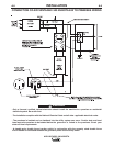
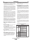
*&*>;C064&43D2C8>=4E824"
(#& ('On the front panel of the AIR VAN-
TAGE® 500 KUBOTA are two indicator lights. A red
light when lit indicates
OCV(Open Circuit Voltage) is
equal to or
greater than 30V and a green light when
lit indicates
OCV(Open Circuit Voltage)
is less than
30V.
The VRD “On/Off” switch inside the control panel
must be “On” for the VRD function to be active and
the lights to be enabled. When the machine is first
started with VRD enabled, both lights will illuminate
for 5 seconds.
These lights monitor the
OCV(Open Circuit Voltage)
and weld voltage at all times. In the CC-Stick mode
when not welding the green light will illuminate indi-
cating that the VRD has reduced the OCV to less
than 30V. During welding the red light will illuminate
whenever the arc voltage is equal to or greater than
30V. This means that the red and green light may
alternate depending on the weld voltage. This is nor-
mal operation.
If the red light remains illuminated when not welding
in the CC-stick mode, the VRD is not functioning
properly. Please refer to your local field service shop
for service.
If the VRD is turned “On” and the lights don’t come
“On”, refer to the trouble shooting section.
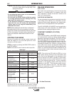
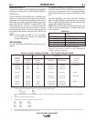
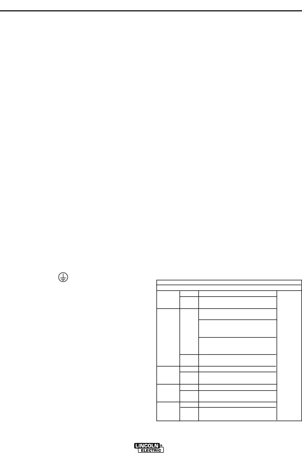
(
VRD INDICATOR LIGHTS
MODE VRD "ON" VRD "OFF"
CC-STICK OCV Green (OCV Reduced)
While Red or Green
Welding (Depends on Weld Voltage) *
CV-WIRE OCV Red (OCV Not Reduced)
Weld Terminals On
Red (OCV Not Reduced)
Weld Terminals Remotely Controlled
Gun Trigger Closed
Green (No OCV)
Weld Terminals Remotely Controlled
Gun Trigger Open No Lights
While Red or Green
Welding (Depends on Weld Voltage) *
PIPE OCV Green (No Output)
While Not Applicable (No Output)
Welding
ARC GOUGING
OCV Green (No Output)
While Not Applicable (No Output)
Welding
TIG OCV Green (Process is Low Voltage)
While Green (Process is Low Voltage)
Welding
* It is normal for the lights to alternate between colors while welding.
&*"(P)#(