


#$&(#"
&*"(P)#(
+ &#$&(#"
)(--
Duty Cycle is the percentage of time the load is being
applied in a 10 minute period. For example a 60% duty
cycle, represents 6 minutes of load and 4 minutes of no
load in a 10 minute period.
(&#"#&!(#"
For any electrode the procedures should be kept with-
in the rating of the machine. For information on elec-
trodes and their proper application see (www.lincoln-
electric.com) or the appropriate Lincoln publication.
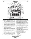
The AIR VANTAGE® 500 KUBOTA can be used with a
broad range of DC stick electrodes. The MODE switch
provides two stick welding settings as follows:
#"'("()&&"('(
+ "
The CC-STICK position of the MODE switch is designed
for horizontal and vertical-up welding with all types of
electrodes, especially low hydrogen. The OUTPUT CON-
TROL dial adjusts the full output range for stick welding.
The ARC CONTROL dial sets the short circuit current (arc-
force) during stick welding to adjust for a soft or crisp arc.
Increasing the number from -10(soft) to +10(crisp) increas-
es the short circuit current and prevents sticking of the
electrode to the plate while welding. This can also increase
spatter. It is recommended that the ARC CONTROL be set
to the minimum number without electrode sticking. Start
with the dial set at 0.
"#( Due to the low OCV with the VRD on, a very
slight delay during striking of the electrodes may
occur. Due to the requirement of the resistance in the
circuit to be low for a VRD to operate, a good metal-
to-metal contact must be made between the metal
core of the electrode and the job. A poor connection
anywhere in the welding output circuit may limit the
operation of the VRD. This includes a good connec-
tion of the work clamp to the job. The work clamp
should be connected as close as practical to where
the welding will be performed.
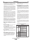
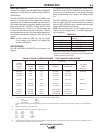
>A"4F;42CA>34B
(
*($:F
&$!0;A 8C4ABA
.69(2.6)
.90(3.4)
1.04(3.9)
2.54(9.6)
1.71(6.5)
2.28(8.6)
1.42(5.4)
3.09(11.7)
2.19(8.3)
&D==8=6(8<45>A
0; 7>DAB
36.23
27.78
24.04
9.84
14.62
10.96
17.60
8.09
11.42
Low Idle - No Load
1425 R.P.M.
Low Idle - 1425 R.P.M.
Air Compressor
40 CFM @ 100PSI
High Idle - No Load
1850 R.P.M.
DC CC Weld Output
500 Amps @ 40Volts
Auxiliary Power 12,000 VA
Auxiliary Power 20,000 VA
Air Compressor
60 CFM @ 100 PSI
Air Compressor
60 CFM @ 100 PSI
and DC, CC Weld
Output 500 Amps
@40 Volts
Air Compressor
60 CFM @ 100 PSI
and Auxiliary Power
12,000
"#( This data is for reference only. Fuel consumption is
approximate and can be influenced by many factors, including
engine maintenance, environmental conditions and fuel quality.
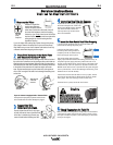
(-$ &*"(P)#() #"')!$(#"
"#(: If the unit fails to start turn Run/Stop switch
to off and repeat step 3 through step 7 after
waiting 30 seconds.
O>=>C0;;>FC74BC0AC4A<>C>AC>AD=2>=C8=D>DB;H
5>A<>A4C70=B42>=3B
O>=>C?DB7C74'(&(1DCC>=F78;4C744=68=4
8BAD==8=61420DB4C78B20=30<064C74A8=6
640A0=3>AC74BC0AC4A<>C>A
OC74=68=4$A>C42C8>=>A0CC4AH70A68=6
867CB3>U=>CVCDA=>55B7>AC;H05C4ABC0AC8=6C74
4=68=4B7DC>55C744=68=48<<4380C4;H0=3
34C4A<8=4C7420DB4
--------------------------------------------------------------------------------
"#(: When starting for the first time, or after and
extended period of time of not operating, it will take
longer than normal to start because the fuel pump has
to fill the fuel system. For best results, bleed the fuel
system as indicated in Maintenance Section of this
manual.
'(#$$"(""
Remove all welding and auxiliary power loads and
allow the engine to run at low idle speed for a few
minutes to cool the engine.
'(#$the engine by placing the RUN-STOP switch in
the STOP position.
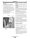
"#(
A fuel shut off valve is located on the fuel pre-filter.
)(#"