


$& "
When paralleling machines in order to combine their
outputs, all units must be operated in the CC-STICK
mode only at the same output settings. To achieve
this, turn the WELD MODE switch to the CC-STICK
position. Operation in other modes may produce errat-
ic outputs, and large output imbalances between the
units.
), &-$#+&#$&(#"
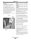
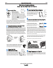
If a GFCI receptacle is tripped, See the MAINTE-
NANCE section for detailed information on testing and
resetting the GFCI receptacle.
Start the engine and set the IDLER control switch to
the desired operating mode. Full power is available
regardless of the welding control settings, if no weld-
ing current is being drawn.
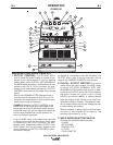
The auxiliary power of the AIR VANTAGE® 500 KUB-
OTA consists of two 20 Amp-120VAC single phase (5-
20R) GFCI duplex receptacles, one 50 Amp-
120/240VAC single phase (14-50R) receptacle and
one 50 Amp 240VAC three phase (15-50R) recepta-
cle. The 120/240VAC receptacle can be split for single
phase 120 VAC operation.
The auxiliary power capacity is 12,000 watts of 60 Hz,
single phase power or 20,000 watts of 60Hz, three
phase power. The auxiliary power capacity rating in
watts is equivalent to volt-amperes at unity power fac-
tor.
The maximum permissible current of the 240 VAC
output is 50 A. The 240 VAC single phase output can
be split to provide two separate 120 VAC outputs with
a maximum permissible current of 50 A per output to
two separate 120 VAC branch circuits. Output voltage
is within ± 10% at all loads up to rated capacity.
N#( The two 120V GFCI modules, receptacles and
the two 120V circuits of the 120/240V receptacle are
connected to different phases and cannot
be paral-
leled.
The auxiliary power receptacles should only be used
with three wire grounded type plugs or approved dou-
ble insulated tools with two wire plugs.
The current rating of any plug used with the system
must be at least equal to the current capacity of the
associated receptacle.
'!) ("#)'+ ""),
&-$#+& #'
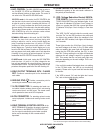
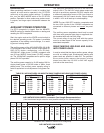
It must be noted that the above auxiliary power ratings
are with no welding load. Simultaneous welding and
power loads are specified in table B.5. The permissi-
ble currents shown assume that current is being
drawn from either the 120 VAC or 240 VAC supply
(not both at the same time).
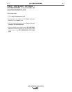
&*"(P)#(GC4=B8>=>A3 4=6C7&42><<4=30C8>=B
(Use the shortest length extension cord possible sized per the following table.)
&*"(P)#(
#$&(#"
(
( &*"(P)#('!) ("#)'+ ""$#+& #'
+
!$'
0
100
200
250
300
400
500
$'
+((' !$'
12,000 50
12,000 50
12,000 50
12,000 50
10,000 42
5,600 23
0 0
$'
+((' !$'
20,000 50
17,800 43
14,000 34
12,000 29
10,000 24
5,600 13
0 0
#("$'
+((' !$'
------ 50
------ 50
------ 50
12,000 ------
10,000 ------
5,600 ------
0 0
$ )'
#&
#&
Current
(Amps)
15
15
20
20
25
30
38
50
Voltage
(Volts)
120
240
120
240
240
240
240
240
Load
(Watts)
1800
3600
2400
4800
6000
7200
9000
12000
30
60
(9)
(18)
40
75
30
60
(12)
(23)
(9)
(18)
75
150
50
100
90
75
(23)
(46)
(15)
(30)
(27)
(23)
125
225
88
175
150
120
100
(38)
(69)
(27)
(53)
(46)
(37)
(30)
175
350
138
275
225
175
150
125
(53)
(107)
(42)
(84)
(69)
(53)
(46)
(38)
300
600
225
450
250
300
250
200
(91)
(183)
(69)
(137)
(76)
(91)
(76)
(61)
Maximum Allowable Cord Length in ft. (m) for Conductor Size
Conductor size is based on maximum 2.0% voltage drop.
14 AWG 12 AWG 10 AWG 8 AWG 6 AWG 4 AWG