


(&#) '##("
Observe all Safety Guidelines detailed throughout this manual
If for any reason you do not understand the test procedures or are unable to perform the tests/repairs safely, contact your
>20; 8=2>;=DC7>A8I4384;3'4AE824028;8CH for technical troubleshooting assistance before you proceed.
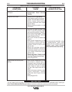
)(#"
$&# !'
'-!$(#!'
$#''
)'
&#!!"
#)&'#(#"
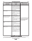
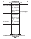
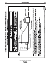
The welding arc is “cold.” The weld-
ing arc is not stable or is not satis-
factory. the engine runs normally.
The auxiliary power is normal.
No output in Pipe Mode.
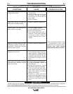
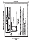
VRD Lights don’t light up.
1. Make sure the MODE selector
switch is in the correct position for
the process being used. (For exam-
ple, CV-WIRE, PIPE, CC-STICK.)
2. Make sure the electrode (wire, gas,
voltage, current etc.) is correct for
the process being used.
3. Check for loose or faulty connec-
tions at the weld output terminals
and welding cable connections.
4. The welding cables may be too long
or coiled, causing an excessive
voltage drop.
5. Faulty Control Board.
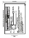
1. Make sure VRD ON/OFF toggle
switch is in the “OFF” position.
2. Poor work lead connection to
work. Make sure work clamp is
tightly connected to clean base
metal.
3. "Weld Terminals" switch in wrong
position. Place switch in "Weld
Terminals On" position when
welding without control cable.
4. Faulty PC board or welder alterna-
tor.
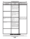
1. Ensure VRD ON/OFF switch is in
the “ON” position.
2. If light is burned out, replace both
VRD lights.
3. Faulty OCV indicator PC board.
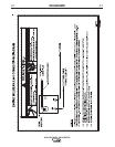
If all recommended possible areas of
misadjustment have been checked
and the problem persists, >=C02C
H>DA;>20; 8=2>;=DC7>A8I43
84;3'4AE824028;8CH
&*"(P)#(