


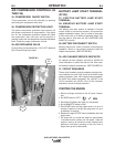
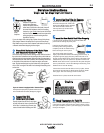

E6010 - Touch, Lift to Start the Arc
E7018, E7024 - Touch, Rock Back and Forth in Joint,
Lift .
Once the arc is started, normal welding technique for
the application is then used.
>A&4'CA8:8=6;42CA>34B
Some electrodes form a cone at the end of the elec-
trode after the welding arc has been broken, particu-
larly iron powder and low hydrogen electrodes. This
cone will need to be broken off in order to have the
metal core of the electrode make contact.
E6010 - Push, Twist in Joint, Lift
E7018, E7024 - Push, Rock Back and Forth in Joint,
Lift.
Once the arc is started, normal welding technique for
the application is then used.
For other electrodes the above techniques should be
tried first and varied as needed to suit operator prefer-
ence. The goal for successful starting is good metal to
metal contact.
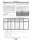
For indicator light operation, see table B.1.
#+" $$+ "
This slope controlled setting is intended for "out-of-posi-
tion" and "down hill" pipe welding where the operator
would like to control the current level by changing the arc
length.
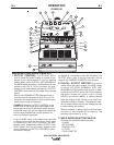
The OUTPUT CONTROL dial adjusts the full output
range for pipe welding.
The ARC CONTROL dial sets the short circuit current
(arc-force) during stick welding to adjust for a soft or
more forceful digging arc (crisp). Increasing the number
from -10(soft) to +10(crisp) increases the short circuit
current which results in a more forceful digging arc.
Typically a forceful digging arc is preferred for root and
hot passes. A softer arc is preferred for fill and cap pass-
es where weld puddle control and deposition (“stacking”
of iron) are key to fast travel speeds. This can also
increase spatter.
It is recommended that the ARC CONTROL be set to the
minimum number without electrode sticking. Start with
the dial set at 0.
"#( With the VRD switch in the “ON” position there is
no output in the DOWNHILL PIPE mode.
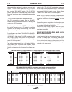
For indicator
light operation, see table B.1.
#$&(#"
&*"(P)#(
(+ "
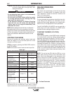
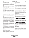
The TOUCH START TIG setting of the MODE switch is
for DC TIG (Tungsten Inert Gas) welding. To initiate a
weld, the OUTPUT CONTROL dial is first set to the
desired current and the tungsten is touched to the work.
During the time the tungsten is touching the work there is
very little voltage or current and, in general, no tungsten
contamination. Then, the tungsten is gently lifted off the
work in a rocking motion, which establishes the arc.
When in the TOUCH START TIG mode and when a
Amptrol is connected to the 6-Pin connector the OUT-
PUT CONTROL dial is used to set the maximum cur-
rent range of the current control of the Amptrol.
The ARC CONTROL is not active in the TIG mode. To
STOP a weld, simply pull the TIG torch away from the
work.
When the arc voltage reaches approximately 30 Volts
the arc will go out and the machine will reset the cur-
rent to the Touch Start level.
To reinitiate the arc, retouch the tungsten to the work
and lift. Alternatively, the weld can be stopped by
releasing the Amptrol or arc start switch.
The AIR VANTAGE® 500 KUBOTA can be used in a
wide variety of DC TIG welding applications. In gener-
al the ‘Touch Start’ feature allows contamination free
starting without the use of a Hi-frequency unit. If
desired, the K930-2 TIG Module can be used with the
AIR VANTAGE® 500 KUBOTA . The settings are for
reference.
AIR VANTAGE® 500 KUBOTA settings when using
the K930-2 TIG Module with an Amptrol or Arc Start
Switch:
• Set the MODE Switch to the TOUCH START TIG
setting.
• Set the "IDLER" Switch to the "AUTO" position.
• Set the "WELDING TERMINALS" switch to the
"REMOTELY CONTROLLED" position.
This will keep the "Solid State" contactor open and provide a
"cold" electrode until the Amptrol or Arc Start Switch is pressed.
When using the TIG Module, the OUTPUT CONTROL on the
AIR VANTAGE® 500 KUBOTA is used to set the maximum
range of the CURRENT CONTROL on the TIG Module or an
Amptrol if connected to the TIG Module.
"#( The TIG process is to receive a low voltage welding
process. There is no difference in operation with the
VRD “On” or “Off” for this mode. For indicator light oper-
ation, see table B.1.