


A-3
INSTALLATION
V205-T DC & V205-T AC/DC TIG
A-3
3. Be sure the torch and work cable rubber cover-
ings are free of cuts and cracks that allow high
frequency leakage. Cables with high natural rub-
ber content, such as Lincoln Stable-Arc
®
better
resist high frequency leakage than neoprene and
other synthetic rubber insulated cables.
4. Keep the torch in good repair and all connections
tight to reduce high frequency leakage.
5. The work terminal must be connected to a ground
within ten feet of the welder, using one of the fol-
lowing methods.
a) A metal underground water pipe in direct con-
tact with the earth for ten feet or more.
b) A 3/4” (19mm) galvanized pipe or a 5/8”
(16mm) solid galvanized iron, steel or copper
rod driven at least eight feet into the ground.
The ground should be securely made and the
grounding cable should be as short as possible
using cable of the same size as the work cable, or
larger. Grounding to the building frame electrical
conduit or a long pipe system can result in re-radi-
ation, effectively making these members radiating
antennas.
6. Keep all panels securely in place.
7. All electrical conductors within 50 ft (15.2m) of the
welder should be enclosed in grounded, rigid
metallic conduit or equivalent shielding. Flexible
metallic conduit is generally not suitable.
8. When the welder is enclosed in a metal building,
several earth driven electrical grounds connected
(as in 5b above) around the periphery of the build-
ing are recommended.
Failure to observe these recommended installation
procedures can cause radio or TV interference prob-
lems.
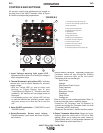
INPUT CONNECTIONS
Be sure the voltage, phase, and frequency of the input
power is as specified on the rating plate, located on
the bottom of the machine.
ELECTRIC SHOCK can kill.
• Have a qualified electrician install
and service this equipment.
• Turn the input power OFF and unplug
the machine from the receptacle
before working on this equipment.
• Allow machine to sit for 5 minutes
minimum to
allow the power capacitors to discharge before
working inside this equipment.
• Do not touch electrically hot parts.
• Machine must be plugged into a receptacle that
is grounded according to the National Electrical
Code and local codes.
• Do not remove or defeat the purpose of the
power cord ground pin.
-----------------------------------------------------------------------
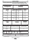
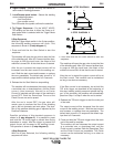
RECONNECT PROCEDURE
The Invertec V205-T DC & V205-T AC/DC auto recon-
nect to either 115V or 230V supply.
This machine is capable of operating within the follow-
ing input voltage ranges (Table A.1):
TABLE A.1
Fuse the input circuit with time delay fuses or delay
type¹ circuit breakers. Using fuses or circuit breakers
smaller than recommended may result in “nuisance”
shut-offs from welder inrush currents even if not weld-
ing at high currents.
The Invertec Power Source is recommended for use
on an individual branch circuit.
¹
Also called “inverse time” or “thermal/magnetic” circuit breakers.
These circuit breakers have a delay in tripping action that
decreases as the magnitude of the current increases.
WARNING
NOMINAL
115V
208V / 230V
RANGE
90-140V
184-276V