


A-6
INSTALLATION
V205-T DC & V205-T AC/DC TIG
A-6
REMOTE CONTROL CONNECTION
A remote control receptacle is provided on the lower
center case front of the welder for connecting a
remote control to the machine. Refer to the Optional
Accessories section of this manual for available
remote controls.
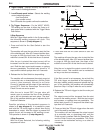
CYLINDER could explode
if damaged.
• Keep cylinder upright and
chained to a support.
• Keep cylinder away from areas where it
could be damaged.
• Never allow the torch or welding electrode
to touch the cylinder.
• Keep cylinder away from live electrical cir-
cuits.
___________________________________________
WARNING
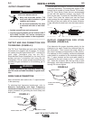
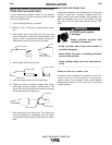
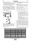
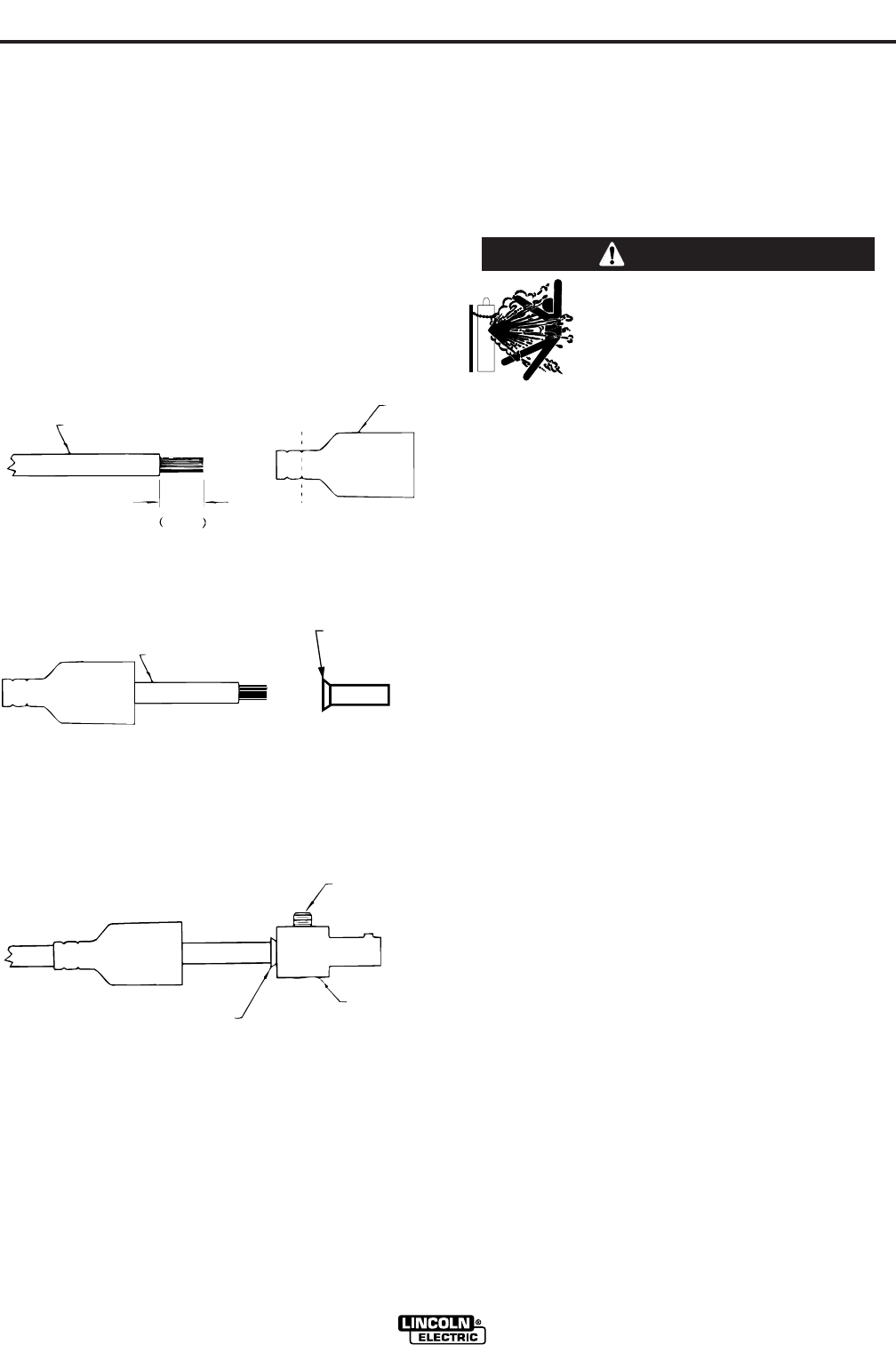
QUICK DISCONNECT PLUG (FOR STICK ELEC-
TRODE CABLE and WORK CABLE)
A quick disconnect system is used for the welding
cable connections. The stick electrode cable will need
to have a plug attached.
1. Cut off welding cable lug, if present.
2. Remove 1.00 in. (25mm) of welding cable insula-
tion.
3. Slide rubber boot onto cable end. The boot end
may be trimmed to match the cable diameter. Use
soap or other nonpetroleum-based lubricant to
help slide the boot over the cable, if needed.
4. Insert copper strands into ferrule.
5. Slide the copper ferrule into the brass plug.
6. Tighten set screw to collapse copper tube. Screw
must apply pressure against welding cable. The
top of the set screw will be well below the surface
of the brass plug after tightening.
7. Slide rubber boot over brass plug. The rubber boot
must be positioned to completely cover all electri-
cal surfaces after the plug is locked into the recep-
tacle.
25 mm
1.00 in.
WELDING CABLE
BOOT
TRIM, IF REQ'D
TO FIT OVER CABLE
WELDING CABLE
COPPER FERRULE
SET SCREW
BRASS PLUG
COPPER TUBE
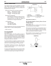
SHIELDING GAS CONNECTION
Obtain the necessary inert shielding gas. Connect the
cylinder of gas with a pressure regulator and flow
gage. Install a gas hose between the regulator and
gas inlet (located on the rear of the welder). The gas
inlet has a 5/16-18 right hand female thread; CGA
#032.