


B-3
OPERATION
B-3
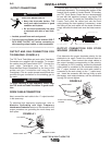
V205-T DC & V205-T AC/DC TIG
1. Input Voltage warning light green LED -
Indicates that the machine is on and input voltage is
within acceptable range.
2. Thermal Shutdown Light (yellow LED) - Indicates
thermal over load or output disabled for incorrect
supply voltage.
• With the "Yellow LED" on, and an alarm code
blinking on "Digital Display Item 6" (see
Troubleshooting Section E, "Possible electrical
problems"), the machine will not supply power at
the output.
• If over-heating occurs, the "Yellow LED" will stay
on until the machine has sufficiently cooled. Leave
the power source on to allow the fan to cool the
unit.
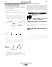
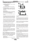
3. Pulse On/OFF push button - CONSTANT current
- PULSED current
4. Setup/Parameter Select push button -
“Setup/Parameter" push button has three (3) differ-
ent functions:
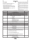
• Access Welding Parameter. Repeatedly pressing the
Parameter button will step through the Welding
Parameter waveform lights on the front panel.
Parameters which can be changed.
Start Current
Upslope
Weld Current (Peak Current)
Pulse Frequency
% on Time
Background Current
Downslope
Finish Current
Postflow sec.
There is a LED for each welding parameter. When lit,
it has confirmed the mode or selection chosen.
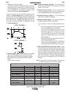
• Access the "AC Frequency" and "AC Balance" by
pressing and holding the Parameter button for three
(3) seconds. (AC/DC model only)
• Access the "Set Up Menu". See Set Up Menu section.
5. Output / Parameter Adjust Knob- Allows you to con-
tinuously adjust the current both in TIG and in Stick
welding. Allows you to change the value, shown on
"Digital Display Item 6", of the parameter selected with
"Setup/Parameter select button Item 4".
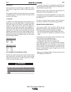
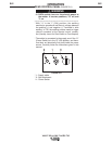
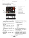
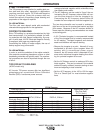
CONTROLS AND SETTINGS
All operator controls and adjustments are located on
the case front of the V205-T machine. Refer to Figure
B.2 and the corresponding explanations.
2. Thermal / Device Warning Light Yellow LED
6. Digital Display
1. Input Voltage warning Light Green LED
5. Output/Parameter Adjust Knob
4. Setup/Parameter Select Button
9. Welding Process (MODE) Button
7. Local/Remote Button
3. Pulse On/Off Button
8.Trigger Selection Button
10. Electrode Connection (Negative)
11. Remote Control Connector
12. Electrode Connection (Positive)
13. Welding Parameter Drawing
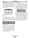
14. VRD (Voltage Reduction Device) Status Light
sec
sec
LOCAL
1
9
10
11
12
13
8
7
6
5
4
3
2
VDR OFF
VDR ON
1
4
FIGURE B.2