


B-7
OPERATION
B-7
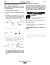
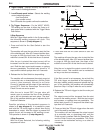
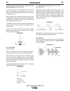
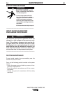
WELDING POLARITY
DC Electrode Negative Polarity (Direct Current
Straight Polarity)
(see FIGURE B.4)
While Welding, there is a continuous flow of electrons
from the electrode to the workpiece.
This is the most used polarity, ensuring limited wear of
the electrode, since the majority of the heat concen-
trates on the anode (workpiece). Narrow and deep
welds are obtained with high travel speeds.
Most materials, with the exception of aluminum and
magnesium, are welded with this polarity.
FIGURE B.4
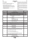
V205-T DC & V205-T AC/DC TIG
OUTPUT LIMITATIONS
The maximum output current as specified in the instal-
lation section of this manual is derated in several situ-
ations; alternate AC Wave Forms, elevated AC
Frequencies and 115V input.
• Alternate AC Wave Forms (See Set Up Menu)¹
Square 200 amps max. output
Sinusoidal 150 amps max. output
Triangular 120 amps max output
• Elevated AC Frequencies¹
Above 85Hz (AC output) the square wave out-
put is limited to 170 amps. Elevated AC
Frequencies do not effect the output of
Sinusoidal and Triangular Waveforms.
• 115V Operation
150 A TIG Mode
110 A Stick Soft mode
100 A Stick Crisp Mode
These derated values have been programmed into the
Invertec V205-T to ensure reliable operation.
¹ AC/DC model only
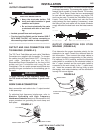
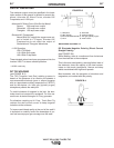
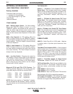
DC TIG WELDING
(see FIGURE B.3)
The TIG (Tungsten lnert Gas) welding process is
based on the presence of an electric arc between a
non-consumable electrode (pure or alloyed tungsten
with an approximate melting temperature of 3370°C)
and the workpiece. An inert gas (typically argon)
atmosphere protects the weld pool.
To avoid inclusions of tungsten in the joint, the elec-
trode should not contact the workpiece. For this rea-
son the arc is started through a Hi. Freq. generator.
For situations requiring no Hi. Freq., Touch Start Tig
reduces the short-circuit current to keep tungsten
inclusions to the minimum.
To improve weld bead quality at the end of the weld it
is important to carefully control the downslope of cur-
rent and ensure proper gas coverage over the weld.
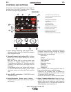
1) Workpiece 5) Flowmeter
2) Filler material 6) Pressure reducer
3) Non-consumable electrode 7
)
l
nert gas (typically argon)
4) Torch 8)
Power source
FIGURE B.3