


B-5
OPERATION
B-5
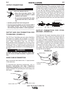
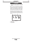
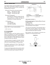
4. Release the TIG torch trigger.
The output current of the machine will turn OFF and
the gas valve will remain open to continue the flow
of the shielding gas. The duration of this postflow
time is adjusted by the Postflow parameter. This
operation is shown in (4 step diagram 1).
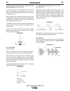
Possible variations of this standard sequence are
shown in (4 step diagram 2). By releasing and re-
pressing the TIG torch trigger during the downslope
step, the output will immediately drop to and hold at
the Finish Current. Releasing the trigger will turn off
the output and begin postflow. This operation shown
in (4 step diagram 2).
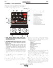
9. Welding selection button - Permits selection of the welding
mode. The LED beside the symbol confirm the selection:
• Stick Crisp-used for E6010 and other cellulosic electrodes
• Stick Soft-used for low Hydrogen and E7018 electrodes
• TIG DC
• TIG AC (AC/DC model only)
10. Electrode Connection (Negative) - For quick disconnect
system using Twist-Mate
TM
cable plugs with gas pass
through for TIG Torches.
11. Remote Control Connector - For the connection of a
Lincoln Foot Amptrol, Hand Amptrol or Arc Start Switch.
See the ACCESSORIES section for available options.
12. Electrode Connection (Positive) - For quick disconnect
system using Twist-Mate
TM
cable plugs
13. Welding Parameter Display - LEDʼs show which mode or
welding parameter is activated for adjustment.
• If it is necessary to modify the welding parameters "Item
13":
- Wait four seconds after the LEDʼs on the panel have
gone out, the welding current LED will be lit.
- Press the SETUP/Parameter push button "Item 4";
every time the push button is pressed, one of the
LEDʼs in the diagram “Item 13” comes on (in clock-
wise sequence) and the value of the parameter
appears on the Digital display "Item 6". Stop at the
desired parameter.
- Rotate the Output/Parameter Adjust Knob"Item 5"
and modify the parameter value.
- Press the SETUP/Parameter "Item 4" push button
again to pass to another parameter, or wait five sec-
onds and the Weld Current LED will come on again.
14. VRD (Voltage Reduction Device) Status Lights- Voltage
reduction device can be enabled from the set-up menu and
an output voltage limit can be set that reduces the output
open circuit voltage when not welding to that limit. If enabled
when the machine is sitting idle the Green VRD on light will
illuminate to indicate the voltage is reduced below the set
limit. If the VRD device is not enabled (factory default) from
the set up menu or while welding the red VRD off light will
illuminate.
Note: The green VRD on light will illuminate in TIG mode until
the output is triggered even when VRD is disabled.
V205-T DC & V205-T AC/DC TIG
4 STEP DIAGRAM 1
4 STEP DIAGRAM 2
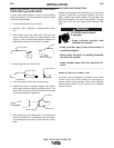
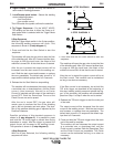
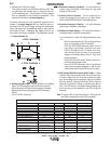
WELDING PARAMETER DEFAULTS AND RANGES
PARAMETER VALUE MIN MAX DEFAULT
START CURRENT AMPS 6 MAX 6
UPSLOPE SEC. 0 10 0.2
WELD CURRENT* AMPS 6 MAX 100
DOWNSLOPE SEC. 0 10 1.0
FINISH CURRENT AMPS 6 MAX 8
POSTFLOW SEC. 0.2 60 5.0
PULSE FREQUENCY HZ 0.1 500 0.5
% ON TIME % 5 95 50
BACKGROUND CURRENT
% OF WELD CURRENT
1 100 20
AC FREQUENCY (AC/DC model only)
HZ 20 150 100
AC BALANCE % EN 35 85 75
(AC/DC model only)
(EN = Electrode Negative)
MODE DC TIG
TRIGGER 2 STEP
LOCAL / REMOTE LOCAL
(1)
(2)
(3)
(4)
* Maximum Weld Current can be limited by input voltage, Welding Mode, AC TIG waveform and AC TIG frequency.