


A-1
INSTALLATION
POWER WAVE F355i (CE)
A-1
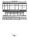
TECHNICAL SPECIFICATIONS -
POWER WAVE F355i
INPUT AC VOLTAGE & DC OUTPUT
Product Ordering Input AC Rated DC Output Output Weight Dimensions
Name Information Voltage Amps/Volts/Duty Cycle Range with Cord HxWxD
(continuous)
POWER K2260-1 380-415 350A / 34V / 60%
14.6” x 17.2” x 27.6”*
WAVE K2260-2 AMPS 110.0 lbs.
(371 x 437 x 701*)mm
F355i 60/50 Hz 5-425 (50.0. kg.)
3 Phase 300A / 32V /100% * Includes Mounting
Brackets
* Overall Length without Mounting Brackets, 21.06” (535mm)
Voltage
380
400
415
Phases
3
3
3
300Amps @
32Volts(100%)
23
22
22
350Amps @
34Volts(60%)
28
27
26
Line Cord
10mm
2
10mm
2
10mm
2
Fuse size
40A
40A
40A
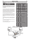
POWER WAVE F355i INPUT CURRENT
OUTPUT CABLES, CONNECTIONS AND LIMITATIONS
Recommended Fuse Sizes Base On The U.S. National Electrical Code And Maximum Machine Outputs
Input 50/60 Hz Output Recommended
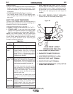
Select The output cable size based upon the following chart.*
Cable sizes for Combined Length of Electrode and Work Cable (Copper) 75C rated:
DUTY CYCLE
100%
60%
CURRENT
300
350
LENGTH UP 200FT.(61m)
2/0
2/0
200-250 FT. (61-76m)
2/0
2/0
*Lincoln Electric recommends using a minimum of 2/0 welding cable for pulse welding.