


5. Replace the wrap around and screws. The PC
board will “read” the switch at power up, and config-
ure the work voltage sense lead appropriately.
ELECTRODE VOLTAGE SENSING
Enabling or disabling electrode voltage sensing is
automatically configured through software. The 67
electrode sense lead is internal to the cable to the
wire feeder and always connected when a wire feeder
is present.
Important: The electrode polarity must be config-
ured on the feed head PC board. Failure to do so
may result in extremely high welding outputs.
------------------------------------------------------------------------
POWER WAVE / POWER FEED WIRE
FEEDER INTERCONNECTIONS
(See Section F-2 for Connection Diagram)
Connect the control cable between the power source
and wire feeder. The wire feeder connection on the
POWER WAVE F355i (CE) is the 14-pin connector
located on the left side of the machine. The control
cable is keyed and polarized to prevent improper con-
nection.
CONTROL CABLE SPECIFICATIONS
It is recommended that genuine Lincoln control cables
be used at all times. Lincoln cables are specifically
designed for the communication and power needs of
the Power Wave / Power Feed system.
The use of non-standard cables, especially in
lengths greater than 25 ft.(7.6m), can lead to com-
muni-cation problems (system shutdowns), poor
motor acceleration (poor arc starting) and low
wire driving force (wire feeding problems).
------------------------------------------------------------------------
HIGH SPEED GEAR BOX
Changing the ratio requires a gear change and a PC
board switch change. The Power Feed Wire Feeders
are shipped with both high speed and a low speed
gears. As shipped from the factory, the low speed
(high torque) gear is installed on the feeder. To
change Gear ratio see Power Feed 10/R Instruction
Manual.
A-4
INSTALLATION
POWER WAVE F355i (CE)
A-4
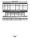
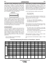
Enable the voltage sense leads as follows:
TABLE A.1
Process Electrode Voltage Work Voltage
Sensing 67 lead * Sensing 21 lead
GMAW 67 lead required 21 lead optional
GMAW-P
67 lead required 21 lead optional
FCAW 67 lead required 21 lead optional
GTAW
Voltage sense at studs Voltage sense at studs
GMAW
Voltage sense at studs Voltage sense at studs
SAW 67 lead required 21 lead optional
CAC-C
Voltage sense at studs Voltage sense at studs
* The electrode voltage 67 sense lead is integral to the
control cable to the wire feeder.
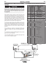
Work Voltage Sensing
The standard POWER WAVE F355i (CE)’s default is
to the work stud (work sense lead disabled).
For processes requiring work voltage sensing, con-
nect the (21) work voltage sense lead (K940) from the
Power Wave work sense lead receptacle to the work
piece. Attach the sense lead to the work piece as
close to the weld as practical, but not in the return cur-
rent path. Enable the work voltage sensing in the
Power Wave as follows:
ELECTRIC SHOCK can kill
• Turn the input power OFF at the
disconnect switch or fuse box
before working on this equipment.
-----------------------------------------------------------
1. Turn off power to the power source at the dis-
connect switch.
2. Remove the wrap around cover from the power
source.
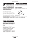
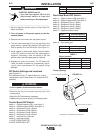
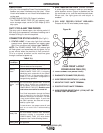
3. The control board is on the center assembly facing
the case front. Locate the 8-position DIP switch and
look for switch 8 of the DIP switch
(See Figure A.1)
.
4. Using a pencil or other small object, slide the switch
to the OFF position if the work sense lead is NOT
connected. Conversely, slide the switch to the ON
position if the work sense lead is present.
WARNING
CAUTION
CAUTION