


viii
viii
TABLE OF CONTENTS
Page
Installation .......................................................................................................Section A
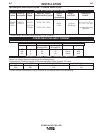
Technical Specifications - POWER WAVE 355 ....................................................A-1
Safety Precautions.................................................................................................A-2
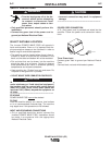
Select Suitable Location ........................................................................................A-2
Stacking ..........................................................................................................A-2
Tilting...............................................................................................................A-2
Input and Grounding Connections ..................................................................A-2
Power Cord Connection..................................................................................A-2
Undercarriage Mountings................................................................................A-2
Output Cables, Connections and Limitations.........................................................A-3
Negative Electrode Polarity ...................................................................................A-3
Voltage Sensing ............................................................................................A-3, A-4
Power Wave to Semi-automatic Power Feed Wire Feeder Interconnections........A-4
Control Cable Specifications..................................................................................A-4
System Description................................................................................................A-5
System Set-Up.........................................................................................A-6 thru A-8
Welding with Multiple Power Waves......................................................................A-9
I / O Receptacle Specifications............................................................................A-10
Dip Switch Settings and Locations...............................................................A-10
Control Board Dip Switch..............................................................................A-10
________________________________________________________________________
Operation .........................................................................................................Section B
Safety Precautions.................................................................................................B-1
General Description...............................................................................................B-1
Recommended Processes and Equipment ...........................................................B-1
Recommended Processes..............................................................................B-1
Required Equipment .......................................................................................B-2
Limitations.......................................................................................................B-2
Duty Cycle and Time Period ...........................................................................B-2
Case Front Controls ................................................................................B-2, B-3
Nominal Procedures........................................................................................B-3
Fringe Procedures...........................................................................................B-3
Making a Weld ................................................................................................B-3
Welding Adjustment ........................................................................................B-3
Constant Voltage Welding...............................................................................B-4
Pulse Welding, Pulse on Pulse (GMAW) ........................................................B-4
Power Mode....................................................................................................B-5
________________________________________________________________________
Accessories.....................................................................................................Section C
Optional Equipment...............................................................................................C-1
Factory Installed..............................................................................................C-1
Field Installed..................................................................................................C-1
Compatible Lincoln Equipment
________________________________________________________________________
Maintenance ....................................................................................................Section D
Safety Precautions ................................................................................................D-1
Capacitor Discharge Procedure ............................................................................D-1
Routine Maintenance.............................................................................................D-1
Periodic Maintenance............................................................................................D-1
Calibration Specification........................................................................................D-1
________________________________________________________________________
Troubleshooting..............................................................................................Section E
How to use Troubleshooting Guide .......................................................................E-1
Using the Status LED to Troubleshoot System Problems.....................................E-2
Troubleshooting Guide.............................................................................E-3 thru E-7
________________________________________________________________________
Wiring Diagram ....................................................................................Section F-1, F-2
Connection Diagram ....................................................................................Section F-3
Dimension Print............................................................................................Section F-4
________________________________________________________________________
Parts Lists................................................................................................................P432
________________________________________________________________________