


In non-synergic modes, the WFS control behaves
more like a conventional CV power source where
WFS and voltage are independent adjustments.
Therefore to maintain the arc characteristics, the oper-
ator must adjust the voltage to compensate for any
changes made to the WFS.
• VOLTS / TRIM:
In constant voltage modes (pulse on pulse GMAW,
standard CV) the control adjusts the welding voltage.
In pulse synergic welding modes (pulse GMAW only)
the user can change the Trim setting to adjust the arc
length. It is adjustable from 0.500 to 1.500. A Trim set-
ting of 1.000 is a good starting point for most condi-
tions.
• WELDING MODE
Selecting a welding mode determines the output char-
acteristics of the Power Wave power source. For a
more complete description of the welding modes
available in the Power Wave and for a complete set of
weld modes programmed into the Power Wave at the
factory, refer to the weld mode print included with the
Power Wave.
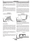
• ARC CONTROL
Also known as Inductance or Wave Control. Allows
operator to vary the arc characteristics from "soft" to
"harsh" in all weld modes. It is adjustable from -10.0 to
+10.0, with a nominal setting of 00.0 (The nominal set-
ting of 00.0 may be displayed as OFF on some Power
Feed wire feeder control panels). See the Welding
Mode descriptions, below, for detailed explanations of
how the Arc Control affects each mode.
B-3
OPERATION
POWER WAVE F355i (CE)
B-3
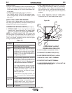
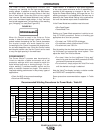
NOMINAL PROCEDURES
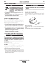
The Power Wave is designed to operate with 3/4"
electrode stick-out for CV and Pulse processes.
FRINGE PROCEDURES
Excessively short or long electrode stick-outs may
function only on a limited basis, if at all.
MAKING A WELD
The serviceability of a product or structure utiliz-
ing the welding programs is and must be the sole
responsibility of the builder/user. Many variables
beyond the control of The Lincoln Electric
Company affect the results obtained in applying
these programs. These variables include, but are
not limited to, welding procedure, plate chemistry
and temperature, weldment design, fabrication
methods and service requirements. The available
range of a welding program may not be suitable
for all applications, and the build/user is and must
be solely responsible for welding program selec-
tion.
------------------------------------------------------------------------
First, consider the desired welding process and the
part to be welded. Choose an electrode material,
diameter, shielding gas and process (GMAW, GMAW-
P, etc.)
Second, find the program in the welding software that
best matches the desired welding process. The stan-
dard software shipped with the Power Waves encom-
passes a wide range of common processes and will
meet most needs. If a special welding program is
desired, contact the local Lincoln Electric sales repre-
sentative.
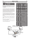
To make a weld, the Power Wave needs to know the
desired welding parameters. The Power Feed (PF)
family of feeders communicate settings to the Power
Wave through control cable connection. Arc length,
wire feed speed, arc control, etc. are all communicat-
ed digitally via the control cable.
• WFS / AMPS:
In synergic welding modes (pulse on pulse GMAW,
pulse GMAW) WFS (wire feed speed) is the dominant
control parameter, controlling all other variables. The
user adjusts WFS according to factors such as weld
size, penetration requirements, heat input, etc. The
Power Wave then uses the WFS setting to adjust its
output characteristics (output voltage, output current)
according to pre-programmed settings contained in
the Power Wave.
WARNING