


When operating with electrode polarity negative the
"Electrode Sense Polarity" DIP switch must be set to the
"Negative" position on the Wire Drive Feed Head PC Board.
The default setting of the switch is positive electrode polari-
ty. Set the Negative Polarity switch on Wire Feed Head PC
board as follows:
ELECTRIC SHOCK can kill
• Turn the input power OFF at the dis-
connect switch or fuse box before
working on this equipment.
• Do not touch electrically hot parts.
-----------------------------------------------------------
1. Turn off power to the power source at the disconnect
switch.
2. Remove the front cover from the power source.
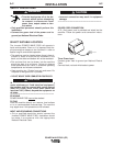
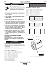
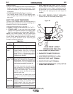
3. The feed head PC board is on the left side of the power
source. Locate the 8-position DIP switch and look for
switch 7 of the DIP switch.(See Figure A.1)
4. Using a pencil or other small object, slide the switch to
the OFF position for positive electrode polarity.
Conversely, slide the switch to the ON position for nega-
tive electrode polarity.
5. Replace the cover and screws. The PC board will“read”
the switch at power up, and configure the work voltage
sense lead appropriately.
VOLTAGE SENSING
The best arc performance occurs when the PowerWaves
have accurate data about the arc conditions. Depending
upon the process, inductance within the electrode and work
lead cables can influence the voltage apparent at the studs
of the welder. Voltage sense leads improve the accuracy of
the arc conditions and can have a dramatic effect on perfor-
mance. Sense Lead Kits (K940-10, -25 or -50) are available
for this purpose.
If the voltage sensing is enabled but the sense
leads are missing, improperly connected, or if the
electrode polarity switch is improperly configured,
extremely high welding outputs may occur.
------------------------------------------------------------------------
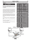
The ELECTRODE sense lead (67) is built into the control
cable, and is automatically enabled for all semi-automatic
processes. The WORK sense lead (21) connects to the
Power Wave at the four pin connector. By default the
WORK voltage is monitored at the output stud in the
POWER WAVE F355i (CE). For more information on the
WORK sense lead (21), see"Work Voltage Sensing” in the
following paragraph.
A-3
INSTALLATION
POWER WAVE F355i (CE)
A-3
OUTPUT CABLES, CONNECTIONS AND
LIMITATIONS
Connect a work lead of sufficient size and length
between the proper output terminal on the power
source and the work. Be sure the connection to the
work makes tight metal-to-metal electrical contact. To
avoid interference problems with other equipment and
to achieve the best possible operation, route all cables
directly to the work or wire feeder. Avoid excessive
lengths and do not coil excess cable.
When using an inverter type power source like the
Power Waves, use the largest welding (electrode
and work) cables that are practical. At least 2/0
copper wire - even if the average output current
would not normally require it. When pulsing, the
pulse current can reach very high levels. Voltage
drops can become excessive, leading to poor
welding characteristics, if undersized welding
cables are used.
------------------------------------------------------------------------
Most welding applications run with the electrode being
positive (+). For those applications, connect the elec-
trode cable between the wire feeder and the positive
(+) output Twist-Mate terminal on the power source.
Connect the other end of the electrode cable to the
wire feeder at it’s proper connection point. Be sure the
connection makes tight metal-to-metal electrical con-
tact. The electrode cable should be sized according to
the specifications given in the output cable connec-
tions section. Connect a work lead from the negative
(-) power source output Twist-Mate terminal to the
work piece. The work piece connection must be firm
and secure, especially if pulse welding is planned.
For additional Safety information regarding the elec-
trode and work cable set-up, See the standard "SAFE-
TY INFORMATION" located in the front of the
Instruction Manuals.
Excessive voltage drops caused by poor work
piece connections often result in unsatisfactory
welding performance.
------------------------------------------------------------------------
NEGATIVE ELECTRODE POLARITY
When negative electrode polarity is required, such as
in some Innershield applications, reverse the output
connections at the power source (electrode cable to
the negative (-) Twist-Mate terminal, and work cable
to the positive (+) Twist-Mate terminal.
CAUTION
CAUTION
CAUTION
WARNING