


CONSTANT VOLTAGE WELDING
Non Synergic CV:
This type of CV mode behaves more like a conventional CV
power source. Voltage and WFS are independent adjustments.
Therefore to maintain the arc characteristics, the operator must
adjust the voltage to compensate for any changes made to the
WFS.
All CV Modes:
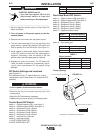
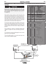
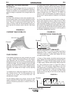
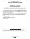
Arc Control, often referred to as wave control, adjusts the induc-
tance of the wave shape. The wave control adjustment is similar
to the "pinch" function in that it is inversely proportional to induc-
tance. Therefore, increasing wave control greater than 0.0
results in a harsher, colder arc while decreasing the wave con-
trol to less than 0.0 provides a softer, hotter arc. (See Figure
B.2)
FIGURE B.2
Current
Time
CURRENT WAVE FORM (CV)
B-4
OPERATION
B-4
POWER WAVE F355i (CE)
The Power Wave utilizes "adaptive control" to compensate
for changes in electrical stick-out while welding. (Electrical
stick-out is the distance from the contact tip to the work
piece.) The Power Wave waveforms are optimized for a
0.75" (19mm) stick-out. The adaptive behavior supports a
range of stickouts from 0.50" (13mm) to 1.25" (32mm). At
very low or high wire feed speeds, the adaptive range may
be less due to reaching physical limitations of the welding
process.
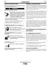
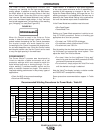
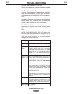
Arc Control, often referred to as wave control, in pulse pro-
grams usually adjusts the focus or shape of the arc. Wave
control values greater than 0.0 increase the pulse frequency
while decreasing the background current, resulting in a tight,
stiff arc best for high speed sheet metal welding. Wave con-
trol values less than 0.0 decrease the pulse frequency while
increasing the background current, for a soft arc good for
out-of-position welding.See Figure B.3)
FIGURE B.3
Current
Time
CURRENT WAVE FORM (PULSE)
PULSE WELDING
Pulse welding procedures are set by controlling an overall
"arc length" variable. When pulse welding, the arc voltage is
highly dependent upon the waveform. The peak current,
back ground current, rise time, fall time and pulse frequency
all affect the voltage. The exact voltage for a given wire feed
speed can only be predicted when all the pulsing waveform
parameters are known. Using a preset voltage becomes
impractical, and instead the arc length is set by adjusting
"trim".
Trim adjusts the arc length and ranges from 0.50 to 1.50,
with a nominal value of 1.00. Trim values greater than 1.00
increase the arc length, while values less than 1.00
decrease the arc length.
All pulse welding programs are synergic. As the wire feed
speed is adjusted, the Power Wave will automatically recal-
culate the waveform parameters to maintain similar arc
properties.
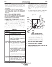
PULSE-ON-PULSE™ (GMAW-PP)
Pulse on Pulse™ is a Lincoln process specifically
designed for use in welding relatively thin (less than
1/4" thick) aluminum. It gives weld beads with very
consistent uniform ripple.
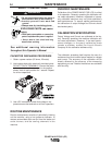
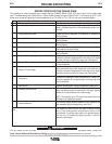
In Pulse on Pulse modes, two distinct pulse types are
used, instead of the single pulse type normally used in
GMAW-P. A number of high energy pulses are used
to obtain spray transfer and transfer metal across the
arc. Such pulses are shown in Figure B.4. After a
number "N" of such pulses, depending on the wire
feed speed used, an identical number "N" of low ener-
gy pulses are performed. These low energy pulses,
shown in Figure B.4, do not transfer any filler metal
across the arc and help to cool the arc and keep the
heat input low.
PEAK
AMPS
BACKGROUND
AMPS
TIME
HIGH HEAT
PULSES
LOW HEAT
PULSES
"N" PULSES "N" PULSES
Current
FIGURE B.4