


A-6
INSTALLATION
POWER WAVE F355i (CE)
A-6
WELDING WITH MULTIPLE POWER
WAVES
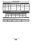
Special care must be taken when more than one
Power Wave is welding simultaneously on a single
part. Arc blow and arc interference may occur or
be magnified.
-----------------------------------------------------------------------
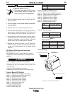
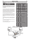
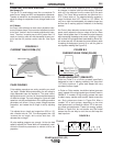
Each power source requires a work lead from the
work stud to the welding fixture. Do not combine all of
the work leads into one lead. The welding travel direc-
tions should be in the direction moving away from the
work lead as shown below. Connect all of the work
sense leads from each power source to the work
piece at the end of the weld. (See Figure A.2)
For the best results when pulse welding, set the wire
size and wire feed speed the same for all the Power
Waves. When these parameters are identical, the
pulsing frequency will be the same, helping to stabilize
the arcs.
Every welding gun requires a separate shielding gas
regulator for proper flow rate and shielding gas cover-
age.
Do not attempt to supply shielding gas for two or more
guns from only one regulator.
If an anti-spatter system is in use then each gun must
have its own anti-spatter system.
I / O RECEPTACLE SPECIFICATIONS
14-Pin Robotic Wire Feeder Connector
Pin Lead Function
A 539 Motor +
B 541 Motor -
C 521 Solenoid +
D 522 Solenoid common
E 845 Tach 2A Differential Signal
F 847 Single Tach input
G 841 +15V Tach Supply
H 844 Tach common
I Open Reserved for future use
J GND Shielding drain
K 842 Tach 1A Differential Signal
L 843 Tach 1B Differential Signal
M 846 Tach 2B Differential Signal
N 67 Electrode Sense (67)
VOLTAGE SENSE RECEPTACLE
PIN LEAD# FUNCTION
3 21 Work Voltage Sense
1 67 Electrode Voltage Sense
RS232 RECEPTACLE
PIN LEAD# FUNCTION
2 253 RS232 Receive
3 254 RS232 Transmit
4 # Pin5
5 # Pin4
6 # # Pin20
20 # # Pin6
7 251 RS232 Common
WIRE FEEDER RECEPTACLE*
PIN LEAD# FUNCTION
A 153 Communiction Bus L
B 154 Communiction Bus H
C 67 Electrode Voltage Sense
D 52 Ovdc -
E 51 +40vdc +
Connect All Work
Sense Leads at the
End of
the
Joint
Connect All Welding
Work Leads at the
Beginning of the Joint
Travel
Direction
P
POWER WAVE F355i
POWER WAVE F355i
TWO POWER WAVES
CAUTION
FIGURE A.2
* Not on Codes 10997
or below.