


A-5
INSTALLATION
POWER WAVE F355i (CE)
A-5
ELECTRIC SHOCK can kill.
• Turn the input power OFF at the
disconnect switch or fuse box
before working on this equipment.
----------------------------------------------------------------------
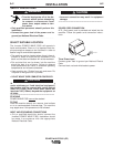
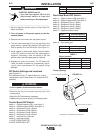
1. Set the High/Low switch code on Feed Head PC
board as follows:
2. Turn off power to the power source at the dis-
connect switch.
3. Remove the front cover from the power source.
4. The wire feed head board is on the left side of the
power source. Locate the 8-position DIP switch and
look for position 8 of the DIP switch.
(See Figure A.1)
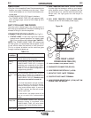
5. Using a pencil or other small object, slide the switch
to the OFF position, when the low speed gear is
installed. Conversely, slide the switch to the ON
position when the high speed gear is installed.
6. Replace the cover and screws. The PC board will
“read” the switch at power up, automatically adjust-
ing all control parameters for the speed range
selected.
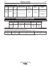
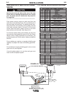
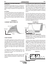
DIP Switch Settings and Locations
(See Figure A.1)
DIP switches on the P.C. Boards allow for custom
configuration of the Power Wave. To access the DIP
switches:
• Turn off power at the disconnect switch.
------------------------------------------------------------------------
• Remove the top four screws securing the front
access panel.
• Adjust the DIP switches as necessary.
• Replace the panel and screws, and restore power.
Control Board DIP Switch:
switch 1 = Object Instance LSB 1 (see table 1)
switch 2 = Object Instance MSB 2 (see table 1)
switch 3 = Equipment Group 1 Select
switch 4 = Equipment Group 2 Select
switch 5 = Equipment Group 3 Select
switch 6 = Equipment Group 4 Select
switch 7 = reserved for future use
switch 8 = work sense lead
1 LEAST SIGNIFICANT BIT
2 MOST SIGNIFICANT BIT
switch 8 work sense lead
off work sense lead not connected*
on work sense lead connected
Feed Head Board DIP Switch:
switch 1 = Object Instance LSB (see table 1)
switch 2 = Object Instance MSB (see table 1)
switch 3 = Equipment Group 1 Select
switch 4 = Equipment Group 2 Select
switch 5 = Equipment Group 3 Select
switch 6 = Equipment Group 4 Select
switch 7 = negative polarity switch
switch 7 electrode polarity
off positive *
on negative
switch 8 = high speed gear
switch 8 wire drive gear
off low speed gear *
on high speed gear
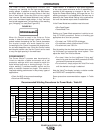
TABLE 1
Object Instance
switch 2 switch 1 Instance
off off 0 *
off on 1
on off 2
on on 3
*Factory Setting
WARNING
WARNING
POWER WAVE F355i
O
N
12345678
O
N
1
23
65478
O
N
1
2
34
5
6
78
O
N
1
23
456
7
8
LOCATION OF DIP SWITCHES IN MACHINE
CONTROL BOARD DIP SWITCH
FEED HEAD BOARD DIP SWITCH
FIGURE A.1